Propos de ce manuel
VCC-ZM300P
Contents
Accessories
Main Features
Precautions
Parts Names and Functions
Parts Names and Functions
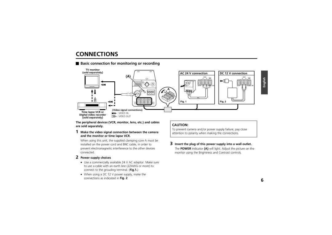
DC 12 V connection
Power supply choices
Connections
AC 24 V connection
Coaxial cable type and maximum length
Connections
Cursor button SET button
Setting to ON, then press the SET button
DISPLAYING/CLOSING the Menu Screen
Sub-menu screen
Menu Item Flow and Menu Operation
Language screen will appear
Language Setting
Interface language becomes French
Camera ID screen
Camera ID Setting
Camera ID setting Example Setting the Camera ID to CAM
ID CAM 1 ????????????
Camera ID Setting
Sync Setting Sync
Power source synchronization L-L setting
SET button
Privacy Mask Setting Privacy Mask
Mask setting
Use the cursor button j or l to select SET for
About the Position screen
Privacy Mask Setting Privacy Mask
To move the cursor to the next * digit
Password setting
Password screen will appear
¤¤¤
Password NEW Password screen will appear
Password Lock cancellation
Password changes
For use when Password Lock is on
Focus setting
Lens Setting Lens
Setting the manual focus Manu
Setting the autofocus Auto
Lens Setting Lens
High High sensitivity focusing LOW Low sensitivity focusing
Button
Available settings OFF, x2, x4, x8, x16 16 power
Zoom setting
Zoom Setting screen will appear
EL Zoom Electronic zoom magnification setting
Iris Auto item Sense UP activated
Mirror Setting
OFF Normal image
View Setting Item Flow
About creating image setting files in View Setting
View Setting Item Flow
Function is set
Iris setting
View Setting
Autoiris setting Auto
BLC Setting screen will appear
View Setting
BLC Setting Size screen will appear
BLC Setting Position screen will appear
BLC Window Weighting screen will appear
Example of setting the mask in the center weighting position
Then press the SET button
Use the cursor button j l d c to move the cursor to
Available settings OFF, x2, x4, x8, x16
Sense UP setting Level setting
Iris Setting screen will appear
Manual iris setting
Sets electronic iris ON/OFF, lens aperture and iris level
AWC One-push automatic white balance
White Balance adjustment
View Setting 1 screen will appear
Available methods ATW Auto trace white balance
White balance additional settings ATW setting
White balance additional settings MWB setting
MWB Setting screen will appear
Use the same steps to place addition masks as needed
White balance additional settings AWC setting
Fast shutter speed Short mode setting
Electronic Shutter setting
Available settings 50, 120, 250, 500, 1000, 2000, 4000
Iris Auto item Sense UP activated or Manu item El on
Slow shutter speed Long mode setting
Blinking
Motion detector setting
Motion Setting screen will appear and SET for Size will
Select ON. Then press the SET button
V2, H1
V1, H1
V2, H2
V1, H2
Finishing motion pattern setting
Motion Masking setting
Pattern
Sensitivity screen will appear
Sensitivity setting
When necessary, adjust the following settings
Detected motion confirmation mode Demo
This item is set in the Motion Setting screen
Interval setting
Alarm Sign setting
Set the vertical profile compensation
Profile compensation setting Aperture
Vertical directions
Set the horizontal profile compensation
Sets AGC to on or OFF and adjusts the gain
Automatic gain control AGC setting
Gain Setting screen will appear, and 0dB will be blinking
Gamma correction setting
Available settings 19200, 9600, 4800
Option Setting
Control setting
RS-485 Setting screen will appear
Alarm setting Alarm input setting Alarm
Option Setting
Address setting
Set the duration for the following alarm input reception
Motion sensor input setting Motion
Alarm duration setting Duration
OFF Does not output a motion sensor alarm
Alarm output setting Alarm OUT
Option Setting
See
Menu Flow
Menu Flow
Electronic zoom
Specifications
Dimensions
Specifications

 Basic connection for monitoring or recording