CL Series Thermal Transfer Printers
Sato CL Series Printers PN 9001035 Rev E
CL Series Printer OPERATOR’S Manual
Preface
Appendices
Table of Contents
Programming
Interface Specifications
UPC-A/EAN-13
Preface
This page left intentionally blank
Section Printer Overview
Introduction
CL408 CL412 CL608 CL612
General Printer Specifications
Printer Overview
Potentiometer Adjustments
Character Fonts
CL408 CL608 CL412 CL612
BAR Codes
MSI Postnet UCC/EAN-128
Power Requirements
Physical
Optional Accessories
Accessory
This page left intentionally blank
Section Installation and Configuration
CL6XX Packaging
Installation and Configuration
Unpacking and Parts Identification
Setting UP the Printer
Loading Labels or Tags
Loading LABELS, Tags and Ribbon
CL608 and CL612
Installation and Configuration
Loading the Ribbon
Sato CL Series Printers 9001035 Rev. E
CL408 and CL412
Loading Labels and Tags
Sensor Assembly
Doors
Label Sensor Adjustments
Operator Panel
Ribbon
Error
Label
Online
To adjust amount of back/forward feed for
Located behind the Front Access Door. Potentiometer
To adjust print darkness fine tuning
To adjust home position of the label +/- 3.75 mm
Label Taken
Option Connector
Status
Threshold
Rear Panel
EXT
External signal connector for Accessories, AMP
Power
Switch to turn power On or Off
Two slots for optional Pcmcia Memory Cards
Switches and Sensors
Front Access Door
Head Open Switch
Top Access Door
Ribbon End Sensor
DSW1-2 DSW1-3
Printer DIP Switch Configuration ALL Models
DSW1-1
DSW1-7 DSW1-8
DSW1-4
DSW1-5 DSW1-6
DSW2-1
DSW2-7
DSW2-4
DSW2-5
DSW2-8
DSW3-6 DSW3-7
DSW3-4
DSW3-5
DSW3-8
Printer Adjustments
Power on
Power , then DSW2-4=ON
User Mode
Print Darkness Setting
Label Feed Direction
Print Speed Adjustment
Pitch Offset and Direction
Sensor Position
Cancel Print Job
Pitch Direction
Zero Slash Setting
Auto Online Setting
CL608 CL612 CL408 CL412 Vertical Offset To1424
Vertical Offset Setting
Horizontal Offset and Direction
HOR. Offset
Direction Label Edge Label Feed Inside
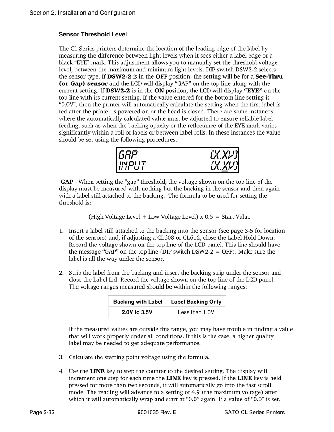
Sensor Threshold Level
Backing with Label Label Backing Only 0V to Less than
Label Only Eye Mark Less than 5V to
Calendar Enabled No YES
Calendar Set
Print Darkness Type
Exit Advanced Mode
Ignore CR/LF
Advanced Mode Counters
Advanced Mode Counters
Print Size
CL608 CL612 CL408 CL412
Installation and Configuration
Potentiometer Adjustments ALL Models
Direction
Sensor Threshold
Potentiometer Adjustments
HEX Dump Diagnostic Labels ALL Models
Print Buffer Hex Dump
Installation and Configuration
Darkness Print
Procedures
Adjusting the Print Quality
Cleaning the Print HEAD, Platen and Rollers
Cleaning and Maintenance
Cleaning the Platen and Rollers
Replacing the Print Head
Cleaning the Sensors
Supplies Needed
Replacing the Fuse
Supplies needed 250V 3A Fuse
Print Potentiometer
Sato SA070 Cleaning Kit
Cleaning the Print Head and Platen
Supplies needed Cleaning the Print Head
Cleaning the Platen
Replacing the Print Head
Re-secure the print head by tightening the screw
ESCCommand Parameter
ESCCommand
ESCCommand Data
Sato CL Programming Language
Selecting Protocol Control Codes
Using Basic
ESC Command Parameter Data
Programming Reference
Open COM19600,E,8,1,CS,DS AS #1
Lprint E$A
Print Area
Print Area
Label Width = 2 x 25.4 mm/in x 12 dpmm = 610 dots
ESCAESCA3H1374V0001
Label Width = 2 x 25.4 mm/in x 8 dpmm = 406 dots
New Base Reference Point = Maximum Print Width Label Width
New Base Reference Point = 1984 dots 610 dots = 1374 dots
ESCH0050ESCV0200ESCB103100*SATO
ESCH0070ESCV0310ESCL0101ESCXUSATO ESCQ1 Escz
Sato Sato
Rotated Fields
Command Default Settings
Command Default
Command Codes
Bar Codes
MSI
Input to Printer
Esca
Printer Output
With Incrementing
UCC-128
Without Incrementing
Special Notes
Bar Codes, Expansion
Command Structure ESCBWaabbb
Command Function
ESCBW02100
Command Structure ESCBTabbccddee
Bar Codes, Variable Ratio
You may use only one variable ratio bar code per label
Code Expansion command see
Individual bar code symbols
ESCA3H100V0050
Command Structure ESCA3H-aaaaVbbbb
Base Reference Point
Printer configuration until a new Base Reference Point
ESCK1H903F
Command Structure Store Command ESCTabcc
Characters, Custom-Designed
Printer Input
Character Expansion see
Character is affected by the following commands
If the printer power is lost
Character Pitch see
Command Structure ESCLaabb
Character Expansion
Until a new expansion command is specified
This command will expand the following fonts
This command will also affect the following commands
Line and Box command, if used within the data stream, may
Spacing
Command Structure
Character, Fixed Spacing
XM, XS, XL and XB
Character Pitch
Label constraints or to enhance readability
Character Expansion command and this command together
This command is affected by the Escl Character Expansion
Command see Page 4-23. The character pitch is actually
This command affects fonts U, S, M, XU, XS, XM, OA & OB see
Character, Proportional Spacing
Reset to fixed spacing
End of the print job unless a reset command is sent
Set to proportional spacing
Special Note
Command Structure ESC*a
Clear Print Jobs & Memory
Command Structure None
Continuous Forms Printing
ESCWDH0100V0050X0600Y0400
Command Structure ESCWDHaaaaVbbbbXccccYdddd
Copy Image Area
For the duplicate image see
ESCNUL0002
Cutter Command
Command Structure ESCNULaaaa
Command Structure Font XU
Fonts U, S, M, OA, OB, XU, XS & XM
Characters may be enlarged through the use of the Character
ESC$=data
Font, Vector
ESC$a,b,c,d
ESC$A,100,200,0ESC$=123456
Font width and height values include asenders, desenders
Pitch command can be used with Vector fonts
Value of 50 is used
Other space
ESCWB1123456
Command Structure Font WB
Fonts WB, WL, XB & XL
Expansion rate is at least 3 times in each direction
Character Expansion command see
Character Pitch command see
Characters may be enlarged through the use of the Escl
Blank label or tag
Form Feed
ESCAspaceESCZ
Form Overlay, Recall
Label image may be stored in this memory area at a time
Loses power, the overlay must be sent again
Form Overlay, Store
Overlay buffer
ESCGH006006
Command Structure ESCGabbbcccdata
Graphics, Custom
Custom graphic cannot be enlarged by the Escl Character
Expansion command
Commands. Therefore, always design and locate your graphic
Custom graphic is not affected by either of the Rotation
Command Structure ESCGPaaaaa,data
Graphics, PCX
Job ID Store
Journal Print
Command, you automatically select Font XS with a Character
Simply issue an Ascii CR at the end of each text line
Expansion of 2x2. You also establish a base reference point
ESCFWaabbVccccHdddd
Lines and Boxes
ESCFWaabcccc
ESCFW02H0200
It is recommended that all lines and boxes be specified
Normal print direction
Line Feed
Sato CL Series Printers 9001035 Rev. E
To be applied to a glass or other transparent surface
Command Structure ESCHhhhhESCVvvvvESCRMaaaa,bbbb
Mirror Image
Reference Point command see Page 4-68. It cannot be used
All data preceding the command will be mirrored
This command can be used with the ESC% Rotate Fixed Base
With the Escr Rotate Moving Base Reference Point command
To an on-line status see Operator Panel in of this
Off-Line mode as soon as the current print job is finished
Off-Line
ESCBP123456789
Command Structure ESCBPn...n
Postnet
Command Structure ESC#Ea
Print Darkness
ESC AX Sets the print length to 14 356 mm
ESC AR Resets the maximum print length to 7 178 mm
Print Length, Expanded
Escax
ESCA3 commands
Print Position
Bbbb
Command Structure ESCQaaaaaa
Print Quantity
Allowable Print Speed settings are as follows
Command Structure ESCCSa
Placement Must be placed immediately after Esca
Print Speed
Duplicate of the previous label will be printed
Repeat Label
To print duplicate of the last label printed
Cycled off and back on since printing the previous label
Changes specified within the current data stream
Replace Data Partial Edit
ESC0 ESCzero
Sato CL Series Printers 9001035 Rev. E
ESC100,50
Command Structure ESCaaaa,bbbb
Reverse Image
Therefore, always assume the printer is in the normal print
Reverse image area is affected by the rotate commands
Orientation when designing and sending the Reverse Image
Command Structure ESC%a
Rotate, Fixed Base Reference Point
Default value
Do not combine this command and the Escr Rotate command
Command is received
See Page 4-70 in the same data stream
Normal Direction Escn
Escn command returns to the original base reference point
Rotate, Moving Base Reference Point
Rotated Direction Escr
Sato CL Series Printers 9001035 Rev. E
ESCF001-001,04,03
Command Structure ESCFaaaabcccc,dd,ee
Sequential Numbering
Value specified for Print Quantity see Page 4-61 should be
Labels, we need 50 total labels. The commands would be as
This command can not be used with the following commands
Equal to the number of different sequential values desired
Start/Stop Label
Calendar Option Commands
Then be printed on the label. This command does not change
Command Structure ESCWPabbb
Placement Anywhere within the data stream Default None
Printer’s internal clock setting
Representative for more details
This command requires the Calendar Option. See your Sato
This command can only be used once per data stream
Once the year increments past 99 it will wrap back to
ESCWAMM/DD/YY hhmm
Command Structure ESCWAelements
Calendar Print
Up to 16 characters can be used with this command
This command can be used up to six times per job
Copy or Reverse Image commands cannot be used with this
This function requires the Calendar Option. See your Sato
ESCWT9101311200
Command Structure ESCWTaabbccddee
Calendar Set
Memory Card Option Commands
Command Structure ESC*a,bb
Memory Card Function Clear Card Memory
Command Structure ESCEXa
Memory Card Function Expand Memory Area
Standard Print Dots Length 178 mm Expanded with Requires
Memory Card Function Fonts, TrueType Recall
ESCBJR1020201000004SATO
ESCBJ50 byte header
Memory Card Function Fonts, TrueType Store
ESCBJDcccccddddee...e
ESCBJD5 byte hex memory offsetdata
ESCYR,01 ESC/D,01,99
Command Structure ESCYR,aa ESC/D,bb,cc...c
Memory Card Function Format/Field Recall
ESCYS,01ESC/N,01,05
Command Structure ESCYS,aaESC/N,bb,cc
Memory Card Function Format/Field Store
Command Structure ESCGRaaa
Memory Card Function Graphics, Custom Recall
Command Structure ESCGIabbbcccddddata
Memory Card Function Graphics, Custom Store
Esca
See the Escpi Store PCX Graphics command
Command Structure ESCPYaaa
This command requires Memory Card option. See your Sato
Memory Card Function Graphics, PCX Recall
ESCPIaaa,bbbbb,data
PCX Graphics Recall command
Memory Card Function Graphics, PCX Store
ESCPI001,32000,data
ESCBJFsatocard
Command Structure ESCBJFaaaaaaaa
Memory Card Function Initialize
Example
Command Structure ESCCCa
Memory Card Function Slot Select
ESCCC1
Memory Card Function Status
Example Escbjs
Example ESCLD,,,%,#,&,*,~,0,0
Custom Protocol Command Codes Download
Command Structure ESCLD,a,b,c,d,e,f,g,h,i
This command must be sent as an independent data stream
Is omitted between two commas, the default Non-Standard
Protocol Command codes for that parameter will be used. See
Preceding the Escz Stop code. No other commands can be
Two-Dimensional Symbols
ESCBX03080505000000001
Two-Dimensional Bar Codes Data Matrix, Data Format
Command Structure ESCBXaabbccddeeefffghh
Printer Outpu
Character SET Encoding Number Scheme
Bit CRC
Two-Dimensional Bar Codes Data Matrix, Print Data
ESCDC00006000
Print Data Command
Two-Dimensional Bar Codes Data Matrix, Sequential Numbering
Command Structure ESCFXaaabcccdddeee
To print sequential numbered Data Matrix symbols
9001035 Rev. E Sato CL Series Printers
Example ESCBV1,2,3,123456789,222,333,MESSAGEESC
Two-Dimensional Bar Codes Maxicode
Command Structure ESCBVa,b,c,ddddddddd,eee,fff,gggg.....ESC
Online Version 5 for the UPS secondary message data format
This command implements Maxicode AIM I.S.S. UPS Version
Symbol
Requirements and the latest format requirements
Command Function Printer Input
Two-Dimensional Bar Codes
Command Structure ESCBKaabbcddeeffffnn...n
ESCBK0304400000021
9001035 Rev. E Sato CL Series Printers
Section Interface Specifications
Interface Types
Single Job Buffer
Interface Specifications
Receive Buffer
Multi Job Buffer
RS232C Serial Interface
General Specifications
Electrical Specifications
PIN Assignments
READY/BUSY Flow Control
On/X-Off Flow Control
Cable Requirements
Data Streams
Stxesca . . Job#1 . . Esczetxstxesca . . Job#n . . Esczetx
BI-DIRECTIONAL Communications
Status Response
STX 2 Byte ID1 Status Byte6 Byte Label RemainingETX
OFF-LINE, Error Condition
Status Byte Definition, Bi-Com Protocol
Centronics Parallel Interface
Data Streams
Accessory EXT Connector
PIN Direction Signal Description
External Output Signal Types
This page left blank intentionally
Initial Checklist
Using the Centronics Parallel Interface
Troubleshooting
ESCA-DATA-ESCZ
Using the RS232C Serial Interface
Error Signals
LED LCD Audible Error Condition To Clear Message Beep
LED1
Message Beep
This page left intentionally blank
Vbbbb
AspaceZ
A3H-aaaa
Babbcccd
Appendix a Command Quick Reference
Eeefffghh
BWaabbb
BXaabbccdd
CSa
FWaaHbbbb
Faaaabcccc
Ddee
FWaabbVccc
Haaaa
Gabbbcccdata
GPaaaaa
IDaa
RMaaaa,bbbb
Paa
Qaaaaaa
WLa
WBa
XccccYdddd
XWa
Aaaa,bbbb
$a,b,c,d
$=data Data for Vector font #Ea
Zero
~aaaa
@ ,nn...n
NULaaaa
WAelements
Ee...e
BJaa..abb..b
BJDcccccdddd
BJFaaaaaaaa
GRcc
EXa
GIabbbcccdd
PIaa,bbbbb
A-12 9001035 Rev. E Sato CL Series Printers
Appendix B BAR Code Specifications
BAR Code Symbologies
ESCD0bbcccd data d
Codabar
ESCB0bbcccd data d Ratio ESCBD0bbcccd data d
Character Set
ESCBD1bbccc* data
Command Structure Ratio ESCB1bbccc* data
Code
ESCD1bbccc* data
ESCD2bbccc data
Interleaved Two of Five I 2/5
ESCBD2bbccc data
Width mils Factor
= Width of narrow element in dots
Narrow Bar
Steps to find the correct check digit
Calculating
Mod 10 Check Digit
ESCD4bbccc data
Command Structure ESCB4bbccc data
Code and the human readable text below the symbol
Check digit is automatically calculated for EAN-8
BD5bbccc data
Industrial Two of Five
B5bbccc data
D5bbccc data
ESCBD6bbccc data
Matrix Two of Five
ESCB6bbccc data
ESCD6bbccc data
See Code 128 Character Table on Page B-18
Command Structure ESCBGbbcccdd data
Density Char/inch Model Dimension Mils Subsets a Subset C
Subset B for 789, then shift to Subset C for
ESCDAbbccc data d
ESCBAbbccc data d
ESCBDAbbccc data d
Ccc Bar height in dots Data
Density Model Dimension Char/inch Ratio Mils
A-Z, -, ., Space, $, /, +, %
Bar code
Command Structure ESCBEbbccc data
ESCDEbbccc data
Command Structure ESCBFbbccc data
Bookland UPC/EAN Supplements
Command Structure ESCBIbbcccd data
UCC-128
B-16 9001035 Rev. E Sato CL Series Printers
Command Structure Escbp data
Sequential Numbering ESCFXaaabcccdddeee
Command Structure Data Format
Data Matrix
Print Data ESCDCxxx...x
Structure of this symbology
ESCBV1,1,2,123456789,840,001,RS01GS961Z01547089
Symbology
ESCAESCV0100ESCH0100
GSUPSNGS056872GS349GS99999999GS001/005
Command Structure ESCBFaabbcddeeffffnnn...n
Code 128 Character Table
Value Subset a Subset B Subset C
Code 128 Character Table
Code 128 Character Table cont’d
Appendix C Custom Characters and Graphics
CUSTOM-DESIGNED Character Example
Appendix C Custom Characters and Graphics
ROW BIT MAP HEX
Sato CL Series Printers 9001035 Rev.E C-3
Custom Graphics Example
Sato CL Series Printers 9001035 Rev.E C-5
C-6 9001035 Rev.E Sato CL Series Printers
Sato CL Series Printers 9001035 Rev.E C-7
PCX Graphics Example
Removing and Unwinding the Roll
Installation
Label Rewinder ALL Models
Label Cutter ALL Models
Appendix D Optional Features
Operator Setup
General Operation
Label Dispense Option
Label Dispenser Routing, CL608/CL612
Label Backing Path, CL408/CL412
Close the Top Access Cover
Label Dispenser Routing, CL408/CL412
D-6 9001035 Rev. E Sato CL Series Printers
Description
Error Handling
Pcmcia Memory Cards
Type
D-8 9001035 Rev. E ATO CL Series Printers
Calendar ALL Models
Interface Card ALL Models
D-10 9001035 Rev. E Sato CL Series Printers
Download Command Structure
Description
Appendix E Custom Protocol Command Codes
Reset
Download Procedure
Sato CL Series Printers 9001035 Rev. E E-3
E-4 9001035 Rev. E Sato CL Series Printers
About Label Wizard
Printers Supported
Appendix F Label Wizard Support