6. Configuration
6. 3. Communication scanner
The communication scanner enables all the
The 8 output variables are assigned using the 8 [Scan.Outp address] (nCAp) parameters. They are configured using the graphic display terminal via the [1.9 - COMMUNICATION]
The 8 input variables are assigned using the 8 [Scan. INp address] (nMAp) parameters. They are configured using the graphic display terminal via the [1.9 - COMMUNICATION]
Enter the logic address of the parameter (see the Parameters Manual).
If a [Scan.Outp address] (nCAp) or [Scan. INp address] (nMAp) parameter equals zero, the corresponding variable is not used by the drive.
These 16 assignment parameters are described in the tables below:
Configuration parameter name | Default assignment of the output variable |
[Scan. Out1 address] (nCA1) | Control word (CMd) |
|
|
[Scan. Out2 address] (nCA2) | Speed reference (LFrd) |
|
|
[Scan. Out3 address] (nCA3) | Not used |
|
|
[Scan. Out4 address] (nCA4) | Not used |
|
|
[Scan. Out5 address] (nCA5) | Not used |
|
|
[Scan. Out6 address] (nCA6) | Not used |
|
|
[Scan. Out7 address] (nCA7) | Not used |
|
|
[Scan. Out8 address] (nCA8) | Not used |
|
|
Configuration parameter name | Default assignment of the input variable |
[Scan. IN1 address] (nMA1) | Status word (EtA) |
|
|
[Scan. IN2 address] (nMA2) | Output speed (rFrd) |
|
|
[Scan. IN3 address] (nMA3) | Not used |
|
|
[Scan. IN4 address] (nMA4) | Not used |
|
|
[Scan. IN5 address] (nMA5) | Not used |
|
|
[Scan. IN6 address] (nMA6) | Not used |
|
|
[Scan. IN7 address] (nMA7) | Not used |
|
|
[Scan. IN8 address] (nMA8) | Not used |
|
|
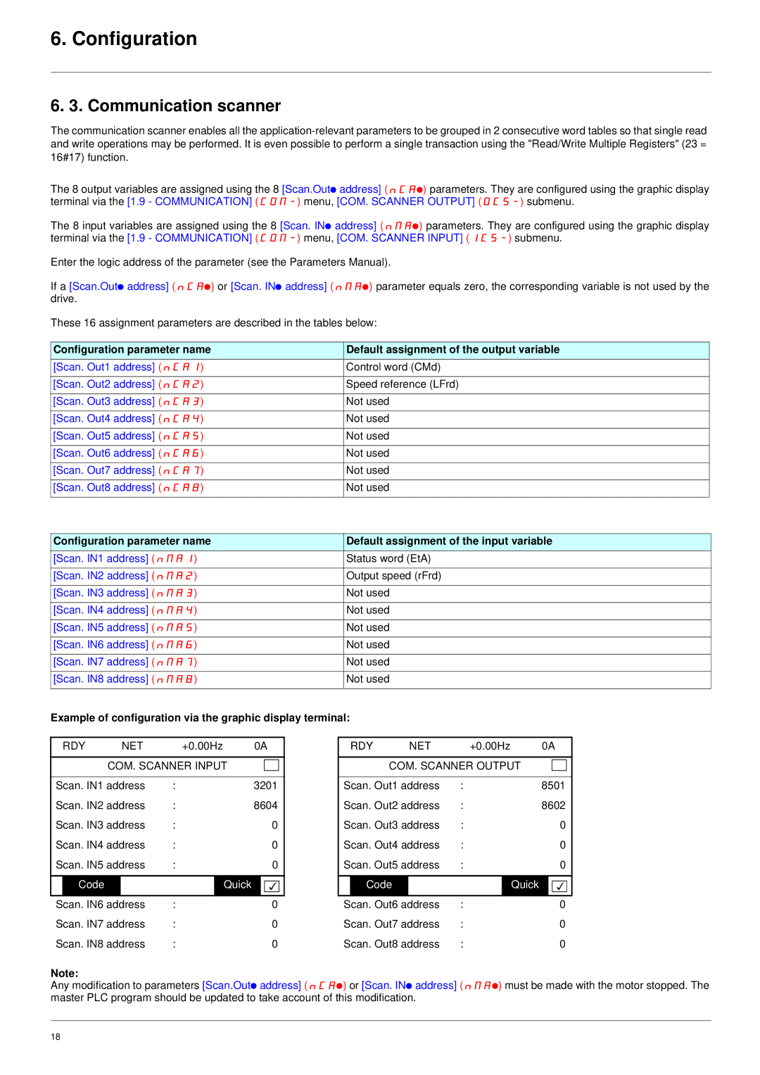
Example of configuration via the graphic display terminal:
| RDY |
| NET |
| +0.00Hz | 0A | ||
|
|
|
|
| ||||
|
| COM. SCANNER INPUT |
|
| ||||
|
|
|
|
| ||||
Scan. IN1 address | : |
|
| 3201 | ||||
Scan. IN2 address | : |
|
| 8604 | ||||
Scan. IN3 address | : |
|
| 0 | ||||
Scan. IN4 address | : |
|
| 0 | ||||
Scan. IN5 address | : |
|
| 0 | ||||
|
|
|
|
|
|
|
|
|
| Code |
|
|
|
| Quick |
|
|
|
|
|
|
|
|
|
| |
Scan. IN6 address | : |
|
| 0 | ||||
Scan. IN7 address | : |
|
| 0 | ||||
Scan. IN8 address | : |
|
| 0 | ||||
| RDY |
| NET |
| +0.00Hz | 0A | ||
|
|
|
|
| ||||
|
| COM. SCANNER OUTPUT |
|
| ||||
|
|
|
|
| ||||
Scan. Out1 address | : |
|
| 8501 | ||||
Scan. Out2 address | : |
|
| 8602 | ||||
Scan. Out3 address | : |
|
| 0 | ||||
Scan. Out4 address | : |
|
| 0 | ||||
Scan. Out5 address | : |
|
| 0 | ||||
|
|
|
|
|
|
| ||
| Code |
|
|
| Quick |
|
| |
|
|
|
|
|
|
|
| |
Scan. Out6 address | : |
|
| 0 | ||||
Scan. Out7 address | : |
|
| 0 | ||||
Scan. Out8 address | : |
|
| 0 | ||||
Note:
Any modification to parameters [Scan.Outp address] (nCAp) or [Scan. INp address] (nMAp) must be made with the motor stopped. The master PLC program should be updated to take account of this modification.
18