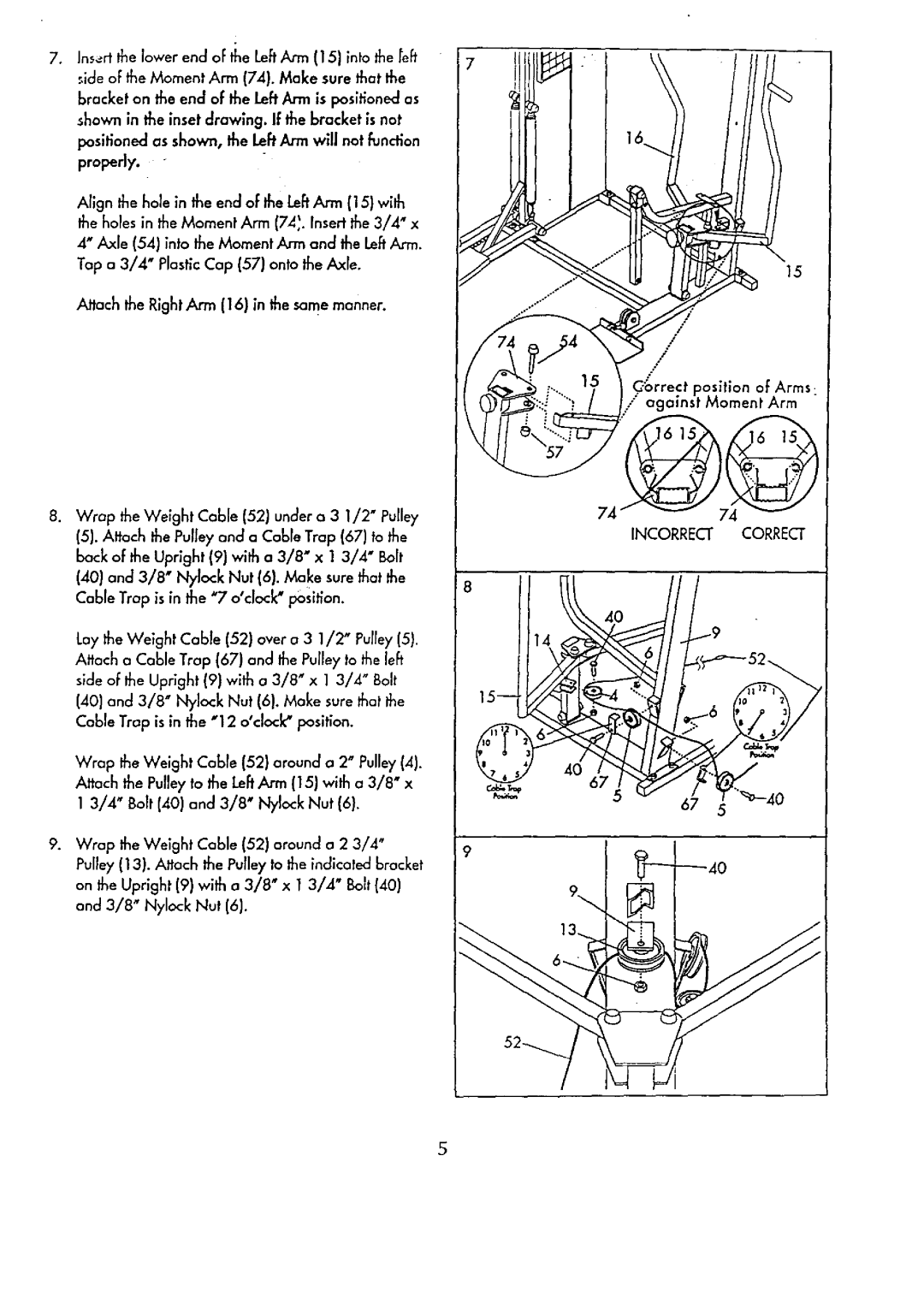
. Insert the lower end oF _neLe[tArm (15) into the refi'
side of the Moment Arm (74). Make sure that the bracket on the end of the Left Arm is positioned as shown in the inset drawing. If the bracket is not positioned as shown, the Left Arm will not function
properly.
Align the hole in the end of the Le[t Arm (15) with the holes in the Moment Arm (74_. Insert the 3/4" x 4" Axle (54) into the Moment Arm and the Left Arm. Tap a 3/4" Plastic Cap (57) onto the Axle.
Attach the Right Arm (16) in the same manner.
. Wrap the Weight Cable (52) under a 3 1/2" Pulley
(5). Attach the Pulley and a Cable Trap (67) to the back of the Upright (9] with a 3/8" x 1 3/4" Bolt
(40)and 3/8" Nylock Nut (6). Make sure that the Cable Trap is in the "7 o'clock" position.
Lay the Weight Cable (52) over a 3 1/2" Pulley (5}. Attach a Cable Trap (67) and the Pulley to the [eft side oF the Upright (9] with a 3/8" x 1 3/4" Bolt (40) and 3/8" Nylock Nut (6). Make sure that the Cable Trap is in the "12 o'cloc_ position.
7
15
/
/
/
/
Cibrrect position of Arms
/ again._t Moment Arm "
74
INCORRECT CORRECT
| Wrap the Weight Cobb (52) around a 2" Pulley (4). |
| |
| Attach the Pulley to the Left ,_'m(15) with a 3/8" x |
| |
| 1 3/4" Bolt (40) and 3/8" Nylock Nut | (6}. |
|
. | Wrap the Weight Cable (52) around a 2 3/4" | 9 | |
| Pulley (13). Attach the Pulley to the indico_ed bracket | ||
|
| ||
| on the Upright (9) with a 3/8" x 1 3/4" | Bolt (40) |
|
| and 3/8" Nylock Nut (6). |
|
|
4O
67
5
67 5
S