_° AI"T._,CHING THE
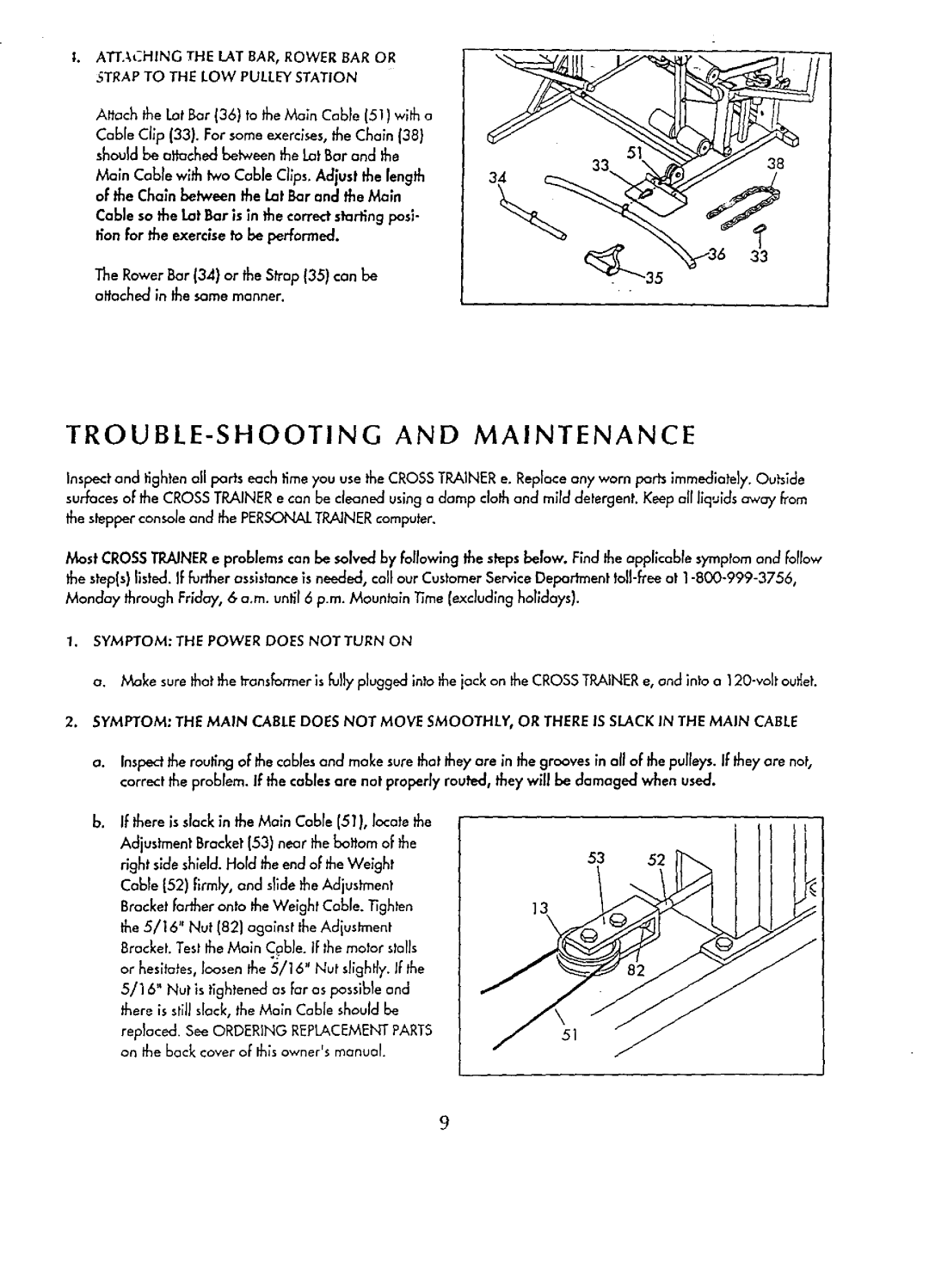
Attach the Lot Bar {36} to the Main Cab}e (51) with a Cable Clip (33). For some exercises, the Chain (38}
should be attached betweenthe LOtBar and the
38
Maln Cable wlth two Cable Clips. Adjust the length34 of the Chain between the Lot Bar and the Main
Cable so the Lot Bar is in the correct starting posi- tion for the exercise to be performed.
33
The Rawer Bar (34} or the Strop (35) can be altached in the same manner.
TROUBLE-SHOOTING AND MAINTENANCE
Inspect and tighten all parts each time you use the CROSSTRAINER e. Replace any worn ports immediately. Outside surfaces of the CROSS TRAINER e can be cleaned using a damp clothand mild detergent. Keep all liquids away Earn the stepper console and the PERSONALTRAINERcomputer.
Most CROSSTRAINER e problems can be salved by follow;ng the steps below. F_ndthe applicable symptom and follow the step(s) listed. If further ossis_nce is needed, coil our Customer Service Department
1.SYMPTOM: THE POWER DOES NOT TURN ON
a. Make sure that the transformer is fully plugged into the jack on the CROSS TRAINERe, and into a
2.SYMPTOM" THE MAIN CABLE DOES NOT MOVE SMOOTHLY, OR THERE IS SLACK IN THE MAIN CABLE
a. Inspectthe routing of the cables and make sure that they are in the grooves in all of the pulleys. If they are not, correct the problem. If the cables are not properly routed, they will be damaged when used.
b, If there is slack in the Main Cable (51}, locate the Adjustment Bracket (53) near the bottom of the right side shleld. Hold the end of the Weight Cable (52) Firmly, and s}ide the Adjustment Bracket farther onto the Weight Cable..tighten the 5/16" Nut (821 against the Adjustment Bracket. Test the Main Cable. IFthe motor stalls or hesitates, loosen the 5/16" Nut slightly, ffthe 5/16" Nut is tightened as Faras Passib}e and there is still slack, the Mo;n Cable should be
replaced. See ORDERING REPLACEMENTPARTS on the back cover oF th_sowner'smanual.
53 52
13\
51
9
