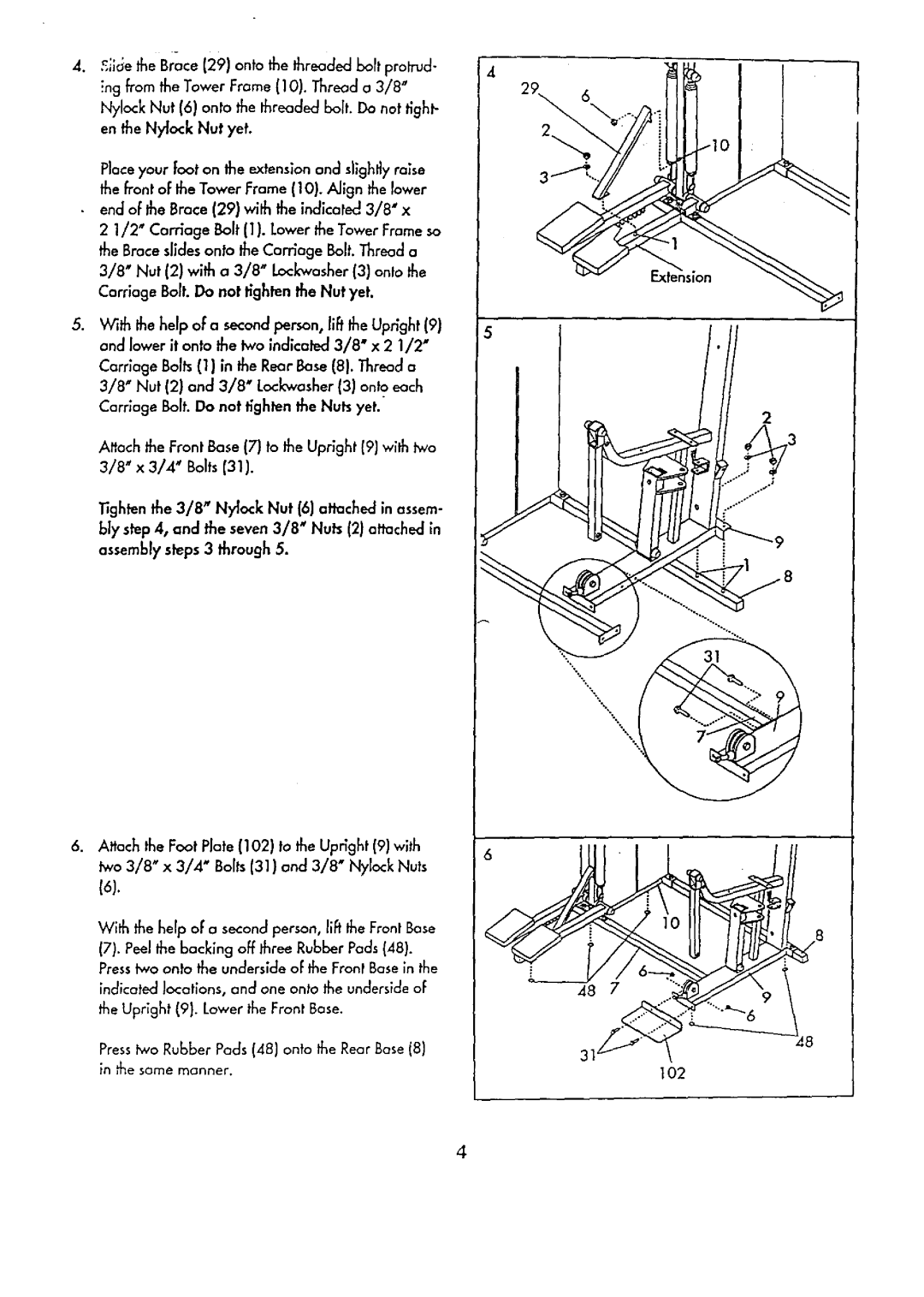
. | ._ilc_ethe Brace (29) | onto the threaded boff protrud- | 4 |
| ing from the Tower Frame (10). Thread a 3/8" |
| |
| Nylock Nut (6) onto | the threaded bolt. Do not tight- |
|
| en the Nytock Nut yet. |
| |
Place your Footon lhe extension and slighl_yraise the front of the Tower Frame (10). Align the lower
•end oFthe Brace (29) with the indicated 3/8" x
2 1/2" Carriage Bolt (1). Lower the Tower Frame so the Brace slidesonto the Corrlage Bolt. Thread a 3/8" Nut (2) with a 3/8" Lack'washer(3) onto the Carriage Bolt. Do not t_ghtenthe Nut yet.
5.With the help of a second person, lift the Upright (9) and lower it onto the two indicaled 3/8" x 2 1/2" Carriage Bolts(1) in the Rear Bose (8). Thread a 3/8" Nut (2} and 3/8" Lockwasher (3) onto each Carriage Bolt. Do not tighten the Nuts yet.
Attach the Front Bose (7) to the Upright (91 with two 3/8" x 3/4" Bolts (31).
Tighten the 3/8" Nylock Nut (6) attached in assem- bly step 4, and the seven 3/8" Nuts (2) attached _n assembly steps 3 through 5.
,Attach the Foot Plate (102) to the Upright (9) with two 3/8" x 3/4" Bolts (31) and 3/8" Nylock Nuts
(6).
With the help of"a second person, lib the Front Base
(7).Peelthe backing off three Rubber Pads (48). Presstwo onto the underside oFthe Front Base in the indicated locations, and one onto the underside oF the Upright (9). Lower the Front Base.
Presstwo Rubber Pods (4B) onto the Rear Base (8) in ,'hesame manner.
29 6\
"\
;\
\.
2
4
