Industry Automation and Drive Technologies - SCE
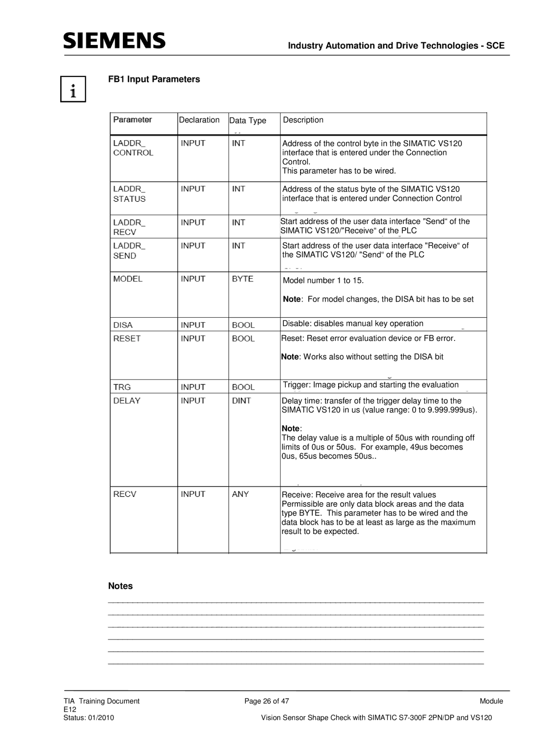
FB1 Input Parameters
Declaration |
| Data Type |
| Description |
|
|
|
|
|
|
|
|
|
|
Address of the control byte in the SIMATIC VS120 interface that is entered under the Connection Control.
This parameter has to be wired.
Address of the status byte of the SIMATIC VS120 interface that is entered under Connection Control
Start address of the user data interface "Send“ of the
SIMATIC VS120/"Receive“ of the PLC
Start address of the user data interface "Receive“ of the SIMATIC VS120/ "Send“ of the PLC
Model number 1 to 15.
Note: For model changes, the DISA bit has to be set
Disable: disables manual key operation
Reset: Reset error evaluation device or FB error.
Note: Works also without setting the DISA bit
Trigger: Image pickup and starting the evaluation
Delay time: transfer of the trigger delay time to the
SIMATIC VS120 in us (value range: 0 to 9.999.999us).
Note:
The delay value is a multiple of 50us with rounding off limits of 0us or 50us. For example, 49us becomes 0us, 65us becomes 50us..
Receive: Receive area for the result values Permissible are only data block areas and the data type BYTE. This parameter has to be wired and the data block has to be at least as large as the maximum result to be expected.
Notes
____________________________________________________________________________
____________________________________________________________________________
____________________________________________________________________________
____________________________________________________________________________
____________________________________________________________________________
____________________________________________________________________________
TIA Training Document | Page 26 of 47 | Module |
E12 |
|
|
Status: 01/2010 | Vision Sensor Shape Check with SIMATIC | |