Industry Automation and Drive Technologies - SCE
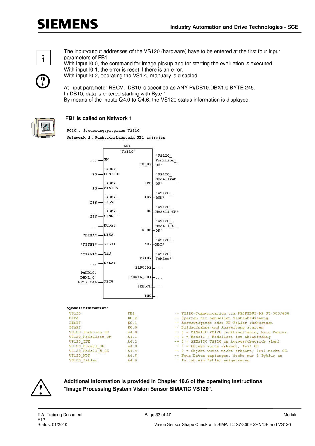
The input/output addresses of the VS120 (hardware) have to be entered at the first four input parameters of FB1.
With input I0.0, the command for image pickup and for starting the evaluation is executed. With input I0.1, the error is reset if there is an error.
With input I0.2, operating the VS120 manually is disabled.
At input parameter RECV, DB10 is specified as ANY P#DB10.DBX1.0 BYTE 245.
In DB10, data is entered starting with Byte 1.
By means of the inputs Q4.0 to Q4.6, the VS120 status information is displayed.
FB1 is called on Network 1
Additional information is provided in Chapter 10.6 of the operating instructions "Image Processing System Vision Sensor SIMATIC VS120“.
TIA Training Document | Page 32 of 47 | Module |
E12 |
|
|
Status: 01/2010 | Vision Sensor Shape Check with SIMATIC | |
