Technical Specifications
7.2Technical Specifications of the ELS TP40M
Attachments
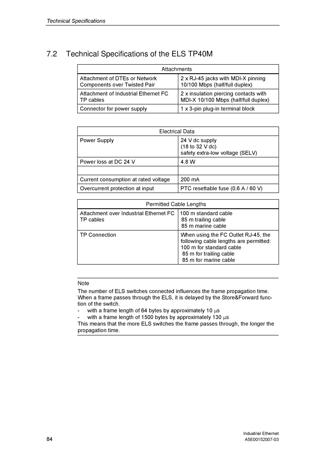
Attachment of DTEs or Network | 2 x |
Components over Twisted Pair | 10/100 Mbps (half/full duplex) |
Attachment of Industrial Ethernet FC | 2 x insulation piercing contacts with |
TP cables | |
Connector for power supply | 1 x |
| |
Electrical Data | |
Power Supply | 24 V dc supply |
| (18 to 32 V dc) |
| safety |
Power loss at DC 24 V | 4.8 W |
|
|
Current consumption at rated voltage | 200 mA |
Overcurrent protection at input | PTC resettable fuse (0.6 A / 60 V) |
| |
Permitted Cable Lengths | |
Attachment over Industrial Ethernet FC | 100 m standard cable |
TP cables | 85 m trailing cable |
| 85 m marine cable |
TP Connection | When using the FC Outlet |
| following cable lengths are permitted: |
| 100 m for standard cable |
| 85 m for trailing cable |
| 85 m for marine cable |
Note
The number of ELS switches connected influences the frame propagation time. When a frame passes through the ELS, it is delayed by the Store&Forward func- tion of the switch.
-with a frame length of 64 bytes by approximately 10 ∝s
-with a frame length of 1500 bytes by approximately 130 ∝s
This means that the more ELS switches the frame passes through, the longer the propagation time.
84 | Industrial Ethernet |
