Installation | DART 300 Modem |
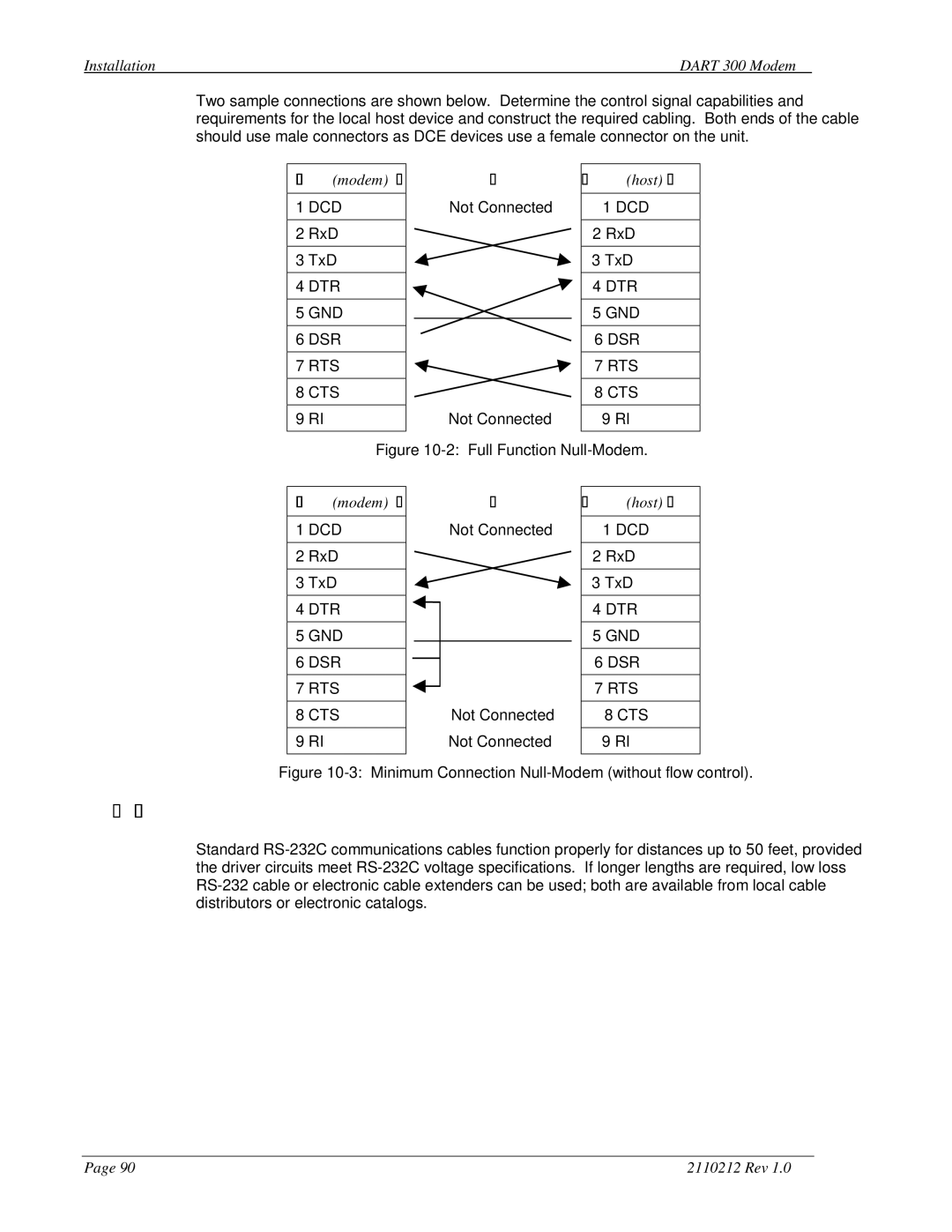
Two sample connections are shown below. Determine the control signal capabilities and requirements for the local host device and construct the required cabling. Both ends of the cable should use male connectors as DCE devices use a female connector on the unit.
DCE (modem)
1DCD
2RxD
3TxD
4DTR
5GND
6DSR
7RTS
8CTS
9RI
Not Connected
Not Connected
DCE (host)
1DCD
2RxD
3TxD
4DTR
5GND
6DSR
7RTS
8CTS
9RI
Figure 10-2: Full Function Null-Modem.
DCE (modem)
1DCD
2RxD
3TxD
4DTR
5GND
6DSR
7RTS
8CTS
9RI
Not Connected
Not Connected Not Connected
DCE (host)
1DCD
2RxD
3TxD
4DTR
5GND
6DSR
7RTS
8CTS
9RI
Figure 10-3: Minimum Connection Null-Modem (without flow control).
10.3.2.Cable Length
Standard
Page 90 | 2110212 Rev 1.0 |