User’s Guide | Device Attachment |
10.3. The Serial Connector
When testing the modem using a PC terminal, the cable is a standard
Pin | Signal | Direction |
|
|
|
1 | DCD – Data Carrier Detect | DCE ! DTE |
|
|
|
2 | RxD – Receive Data | DCE ! DTE |
|
|
|
3 | TxD – Transmit Data | DCE " DTE |
|
|
|
4 | DTR – Data Terminal Ready | DCE " DTE |
|
|
|
5 | GND – Signal Ground | Common |
|
|
|
6 | DSR – Data Set Ready | DCE ! DTE |
|
|
|
7 | RTS – Request to Send | DCE " DTE |
|
|
|
8 | CTS – Clear to Send | DCE ! DTE |
|
|
|
9 | RI – Ring Indicator | DCE ! DTE |
|
|
|
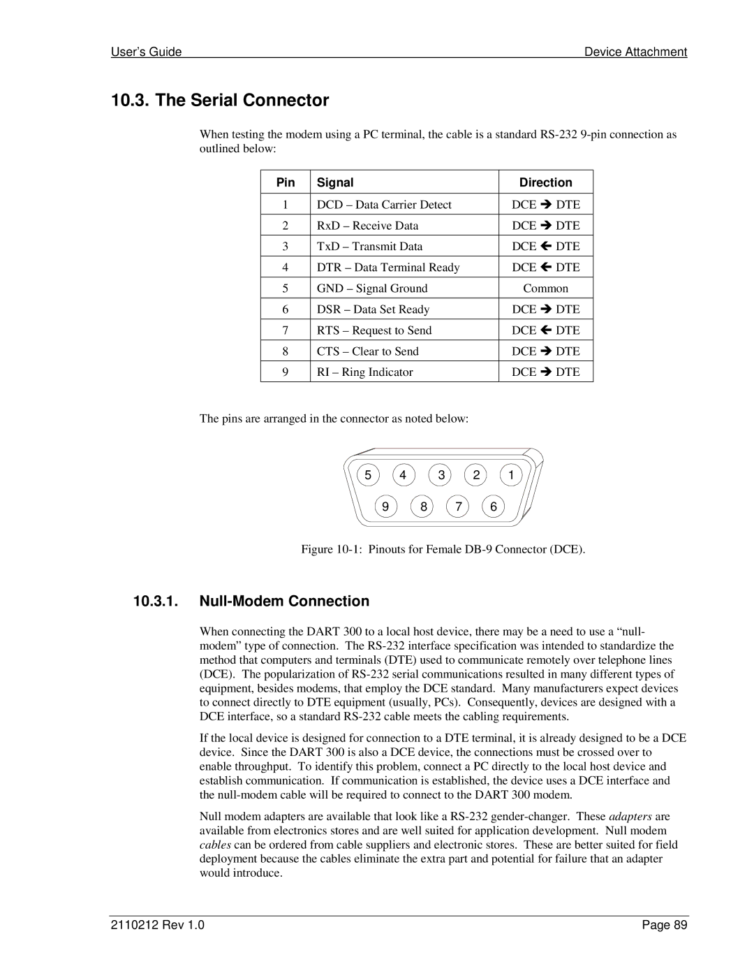
The pins are arranged in the connector as noted below:
5 4 3 2 1
9 | 8 | 7 | 6 |
Figure 10-1: Pinouts for Female DB-9 Connector (DCE).
10.3.1.Null-Modem Connection
When connecting the DART 300 to a local host device, there may be a need to use a “null- modem” type of connection. The
If the local device is designed for connection to a DTE terminal, it is already designed to be a DCE device. Since the DART 300 is also a DCE device, the connections must be crossed over to enable throughput. To identify this problem, connect a PC directly to the local host device and establish communication. If communication is established, the device uses a DCE interface and the
Null modem adapters are available that look like a
2110212 Rev 1.0 | Page 89 |