Directory Structure of Image
Memory
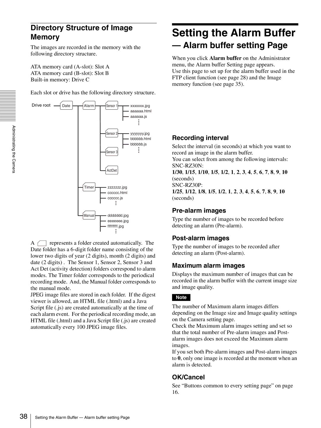
The images are recorded in the memory with the following directory structure.
ATA memory card
ATA memory card
Each slot or drive has the following directory structure.
Drive root | Date | Alarm | Sensor 1 | xxxxxxx.jpg |
|
|
|
| aaaaaa.html |
Administrating |
|
|
| aaaaaa.js |
|
| Sensor 2 | yyyyyyy.jpg | |
|
|
| ||
|
|
|
| bbbbbb.html |
|
|
|
| bbbbbb.js |
the |
|
| Sensor 3 |
|
|
|
|
| |
Camera |
|
| ActDet |
|
|
|
|
| |
|
| Timer | zzzzzzz.jpg |
|
|
|
| cccccc.html |
|
|
|
| cccccc.js |
|
|
| Manual | ddddddd.jpg |
|
|
|
| eeeeeee.jpg |
|
|
|
| ffffffff.jpg |
|
A![]() represents a folder created automatically. The Date folder has a
represents a folder created automatically. The Date folder has a
JPEG image files are stored in each folder. If the digest viewer is allowed, an HTML file (.html) and a Java Script file (.js) are created automatically at the time of each alarm event. For the periodical recording mode, an HTML file (.html) and a Java Script file (.js) are created automatically every 100 JPEG image files.
Setting the Alarm Buffer
— Alarm buffer setting Page
When you click Alarm buffer on the Administrator menu, the Alarm buffer Setting page appears.
Use this page to set up for the alarm buffer used in the FTP client function (see page 28) and the Image memory function (see page 35).
Recording interval
Select the interval (in seconds) at which you want to record an image in the alarm buffer.
You can select from among the following intervals:
1/30, 1/15, 1/10, 1/5, 1/2, 1, 2, 3, 4, 5, 6, 7, 8, 9, 10 (seconds)
1/25, 1/12, 1/8, 1/5, 1/2, 1, 2, 3, 4, 5, 6, 7, 8, 9, 10
(seconds)
Type the number of images to be recorded before detecting an alarm
Type the number of images to be recorded after detecting an alarm
Maximum alarm images
Displays the maximum number of images that can be recorded in the alarm buffer with the current image size and image quality.
Note
The number of Maximum alarm images differs depending on the Image size and Image quality settings on the Camera setting page.
Check the Maximum alarm images setting and set so that the total number of
If you set both
OK/Cancel
See “Buttons common to every setting page” on page 16.
38
Setting the Alarm Buffer — Alarm buffer setting Page
