For Machines Mfg. Since 3/11 | E L E C T R I C A L |
Additional Components
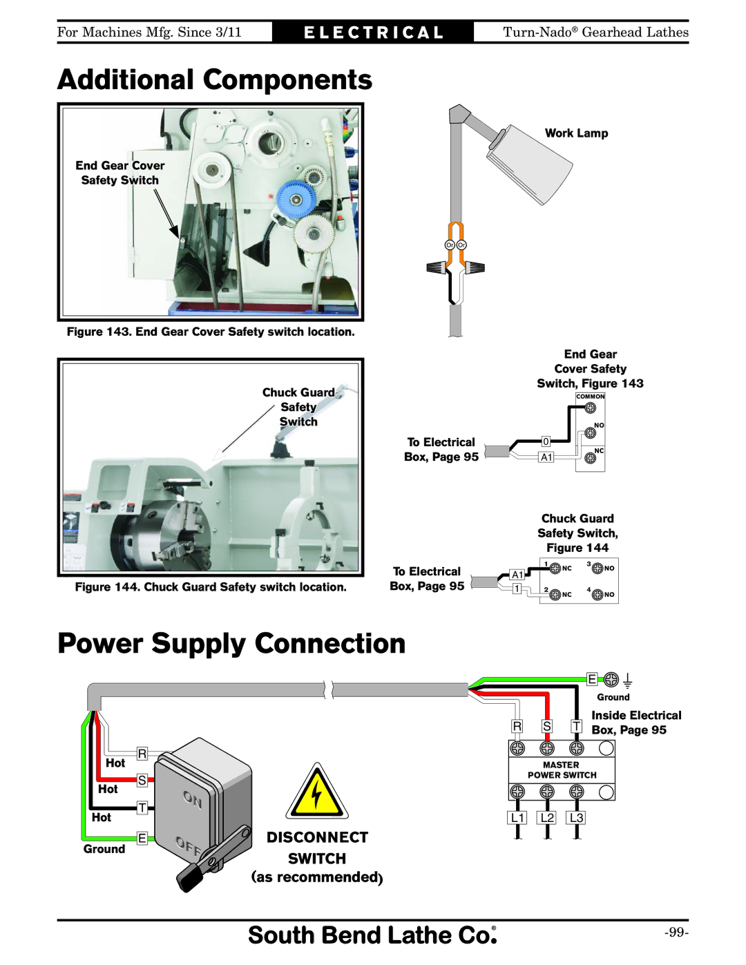
End Gear Cover
Safety Switch
Figure 143. End Gear Cover Safety switch location.

Chuck Guard
Safety
Switch
Figure 144. Chuck Guard Safety switch location.

To Electrical
Box, Page 95
To Electrical
Box, Page 95 ![]()
Work Lamp
additional com- pontnet
End Gear
Cover Safety
Switch, Figure 143
COMMON
NO
0
A1 | NC |
|
Chuck Guard
Safety Switch,
Figure 144
| 1 | NC | 3 | NO |
A1 |
|
| ||
|
|
|
| |
1 | 2 | NC | 4 | NO |
|
|
|
Power Supply Connection
|
|
|
|
|
| E |
|
|
|
|
|
|
|
|
|
|
| ||||||
|
|
|
|
|
|
|
| ||||
|
|
|
|
|
| Ground | |||||
|
|
|
|
|
| Inside Electrical | |||||
R |
| S |
| T |
| Box, Page 95 | |||||
|
|
| |||||||||
Hot
Hot
Hot
Ground
R
S
T
E
DISCONNECT
SWITCH
(as recommended)
MASTER
POWER SWITCH
L1 | L2 | L3 |