Instruction Manual
Hardware Guide
Front Panel
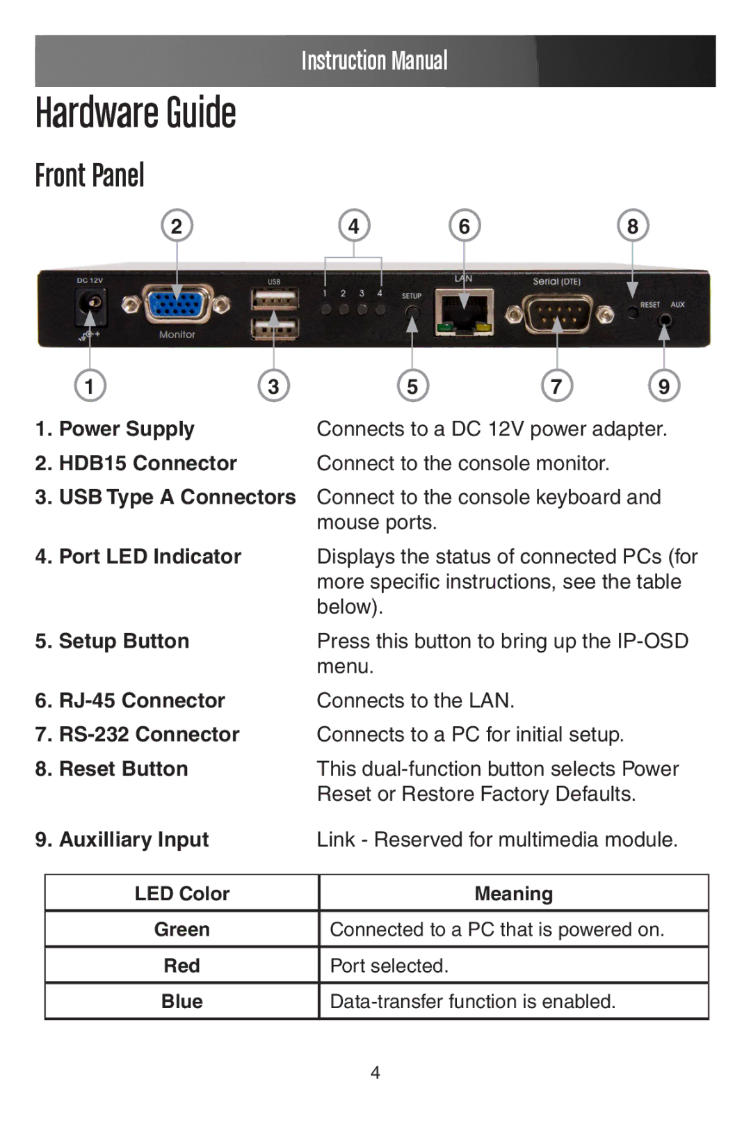
2 | 4 | 6 | 8 |
| 1 | 3 | 5 | 7 | 9 |
1. | Power Supply |
| Connects to a DC 12V power adapter. | ||
2. | HDB15 Connector |
| Connect to the console monitor. |
| |
3.USB Type A Connectors Connect to the console keyboard and mouse ports.
4.Port LED Indicator Displays the status of connected PCs (for more specific instructions, see the table below).
5. | Setup Button | Press this button to bring up the | |
|
|
| menu. |
6. | Connects to the LAN. | ||
7. | Connects to a PC for initial setup. | ||
8. | Reset Button | This | |
|
|
| Reset or Restore Factory Defaults. |
9. | Auxilliary Input | Link - Reserved for multimedia module. | |
|
|
|
|
|
| LED Color | Meaning |
|
|
|
|
|
| Green | Connected to a PC that is powered on. |
|
|
|
|
|
| Red | Port selected. |
|
|
|
|
|
| Blue | |
|
|
|
|
4
