•Optional Ethernet communications
System Component Description
This section describes the various components of the rate monitor system.
Extruder Inductive Proximity Switch
The extruders RPM must be reported to all GH,
This measurement can also be achieved by writing the extruder’s rpm through communications (see document at the end of this manual for details, NOT AVAILABLE FOR
Surge Hopper
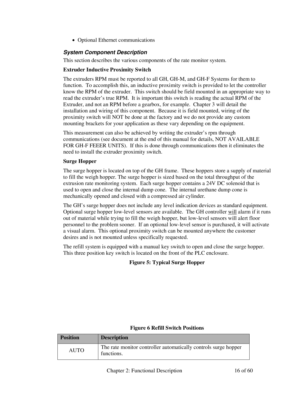
The surge hopper is located on top of the GH frame. These hoppers store a supply of material to fill the weigh hopper. The surge hopper is sized based on the total throughput of the extrusion rate monitoring system. Each surge hopper contains a 24V DC solenoid that is used to open and close the internal dump cone. The internal urethane dump cone is mechanically opened and closed with a compressed air cylinder.
The GH’s surge hopper does not include any level indication devices as standard equipment. Optional surge hopper
The refill system is equipped with a manual key switch to open and close the surge hopper. This three position key switch is located on the front of the PLC enclosure.
Figure 5: Typical Surge Hopper
Figure 6 Refill Switch Positions
Position | Description |
|
|
|
|
| |
AUTO | The rate monitor controller automatically controls surge hopper |
| |
functions. |
|
| |
|
|
| |
|
|
|
|
| Chapter 2: Functional Description | 16 of 60 | |