ICB700TR, ICB700TCI, ICB700TFI specifications
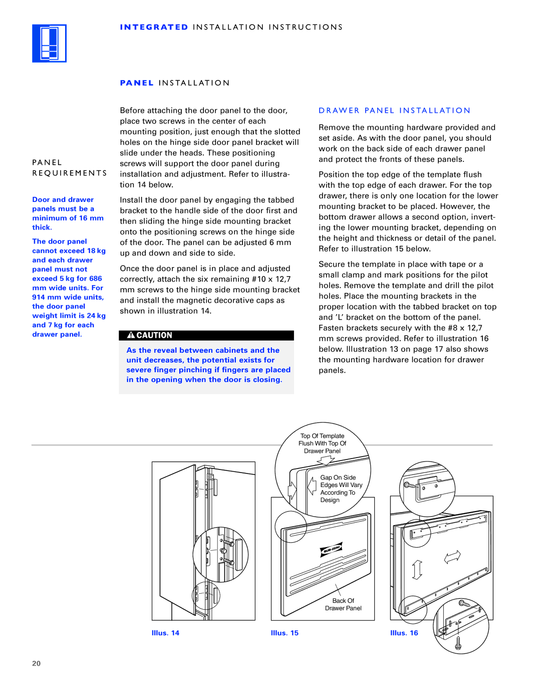
The Sub-Zero ICB700 series comprises three impressive models: ICB700TFI, ICB700TCI, and ICB700TR. Renowned for their commitment to quality and innovation, Sub-Zero has designed these integrated column refrigerators to cater to the discerning needs of culinary enthusiasts and professionals alike.One of the standout features of the ICB700 series is its seamless integration capabilities. With a panel-ready design, these refrigerators can be customized to match existing cabinetry, providing a stunning aesthetic that complements any kitchen layout. This attention to design details ensures that the refrigerators blend effortlessly into their surroundings while offering advanced functionality.
At the heart of the ICB700 series is the Purity technology, which includes an advanced air purification system. This system utilizes a carbon filter to remove ethylene gas, a common agent that accelerates food spoilage. By maintaining optimal air quality within the refrigerator, the Purity system extends the freshness of fruits and vegetables, ensuring that your ingredients remain at their peak for longer periods.
Each model in the ICB700 series is equipped with an advanced cooling system that employs dual-compressor technology. This feature allows for separate temperature control of the refrigerator and freezer compartments. Consequently, it ensures that air circulates uniformly, minimizing temperature fluctuations and preserving the quality of stored food items.
The interior of each ICB700 model is thoughtfully designed for convenience and functionality. Adjustable glass shelves provide flexible storage options, while the soft-close drawers offer easy access to both fresh and frozen items. The organization drawers keep your food neatly in place, allowing for quick identification and access.
Another key feature is the Smart Touch Control panel, which allows users to easily set temperatures and monitor performance. With intuitive controls, users can quickly adjust settings according to their needs, ensuring optimal storage conditions for various food items.
Energy efficiency is also a hallmark of the ICB700 series. These refrigerators are designed to utilize less energy while delivering powerful refrigeration performance, making them a responsible choice for environmentally-conscious consumers.
In summary, the Sub-Zero ICB700TFI, ICB700TCI, and ICB700TR models combine a sleek, integrated design with cutting-edge technologies. Their superior air purification, adjustable interior, advanced cooling systems, and user-friendly controls make them an ideal choice for anyone looking to elevate their culinary experience. This series exemplifies Sub-Zero’s commitment to quality and performance, making it a reliable addition to any kitchen.

