+ii+~~
To an AC Receptacle
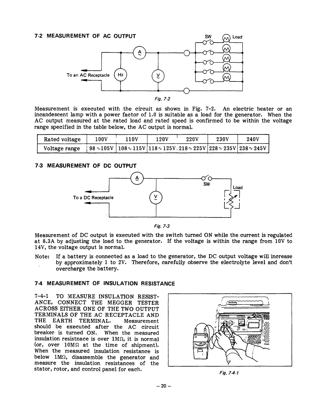
Fig.
Measurement is executed with the circuit as shown in Fig.
range specified in the table below, the AC output is normal.
I1
Rated voltage 1 1OOV 1 1lOV 120v I 220v 230V 240V Voltage range i 98~105V 108~115V~118~125V~218~~225V 228~235V 238~245V
73 MEASUREMENT OF DC OUTPUT
To a DC Receptacle
Fig. 73
Measurement of DC output is executed with the switch turned ON while the current is regulated at 8.3A by adjusting the load to the generator. If the voltage is within the range from 1OVto 14V, the voltage output is normal.
Note: If a battery is connected as a load to the generator, the DC output voltage will increase by approximately 1 to 2V. Therefore, carefully observe the electrolyte level and don’t overcharge the battery.
7-4-l TO MEASURE INSULATION RESIST-
ANCE, CONNECT THE MEGGER TESTER ACROSS EITHER ONE OF THE TWO OUTPUT TERMINALS OF THE AC RECEPTACLE AND
THE EARTH TERMINAL. Measurement should be executed after the AC circuit breaker is turned ON. When the measured insulation resistnace is over lMQ, it is normal (or, over 1OMQ at the time of shipment). When the measured insulation resistance is below lMn, disassemble the generator and measure the insulation resistances of the stator, rotor, and control panel for each.
F&.