9-4-2 PISTON AND PISTON RING
(1)If a ring expander is not available, set the ring joint at the first land of the piston, as shown in Fig.
Note: Be careful not to twist or expand each ring too excessively. The oil ring is fitted onto the piston, followed by the second ring and top ring.
Top Ring
Second Ring
Oil Ring
F&.
(2)The connecting rod is joined to the piston with the piston pin.
Note: Prior to assembly, apply sufficient lub- ricating oil, to the connecting rod minor edge.
Note: Be sure to secure the clips to both sides of the piston pin.
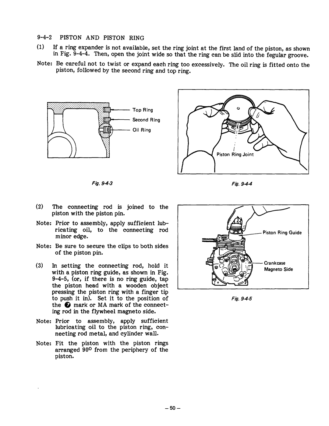
(3)In setting the connecting rod, hold it with a piston ring guide, as shown in Fig.
Note: Prior to assembly, apply sufficient lubricating oil to the piston ring, con- necting rod metal, and cylinder wall.
Note: Fit the piston with the piston rings arranged 90* from the periphery of the piston.
Fig.
Piston Ring Guide
F&T