| j | Part to | 1 |
ISequence I | remOve |
| |
12 | ’Rear | j (1) | |
‘bracket |
|
I | i (2) |
| |
| I |
| / (3) |
| I |
| I |
Description
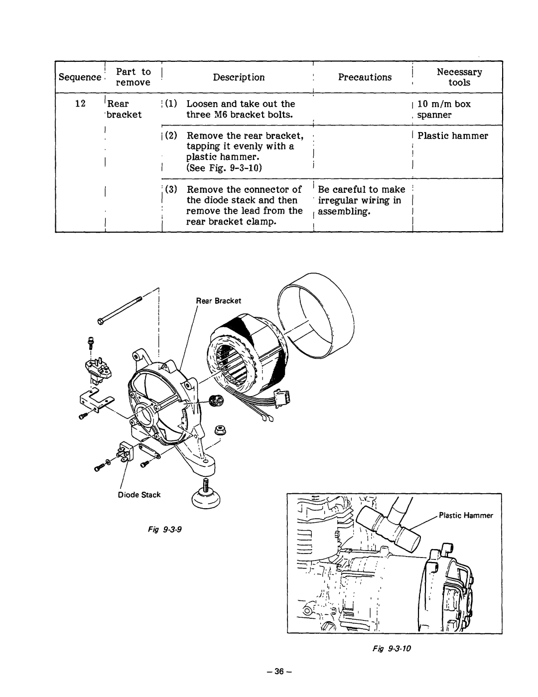
Loosen and take out the three M6 bracket bolts.
Remove the rear bracket, tapping it evenly with a plastic hammer.
(See Fig. g-3-10)
Remove the connector of the d&e stack and then remove the lead from the rear bracket clamp.
Precautions | j | Necessary |
| |
tools | I | |||
|
| |||
|
|
| ||
| 110 m/m box |
| ||
| , spanner |
| ||
a | i Plastic hammer |
| ||
’ | I |
|
| |
| I |
|
| |
I | I |
|
| |
’ Be careful to make j |
|
| ||
irregular wiring in | ( |
|
| |
, assembling. | I |
|
| |
I | 1 |
|
| |
|
|
| ||
Rear Bracket
/
Diode Stack
Plastic Hammer
Fig
