11. FUNCTIONAL CHECK of EACH COMPONENT
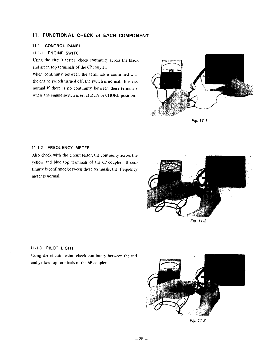
Using the circuit tester. check continuity across the black and green top terminals of the 6P coupler.
When continuity between the termmals is confirmed with the engine switch turn2d off. the switch is normal. It is also normal if there is no continuity between thrse terminals, when the engine switch is set at RUN or CHOKE position.
Fig.
1
Also check with the circuit tester. th2 continuity across the yellow and blue top tsrminals of the 6P coupler. If con- tinuity is confirmed between these terminals. the frequency meter is normal.
Fig. 7
11-1-3 PILOT LIGHT
Using the circuit tester, check continuity between the red and yellow top terminals of the 6P coupler.
Fig. 1
- 25 -
