Table 1
Fig.
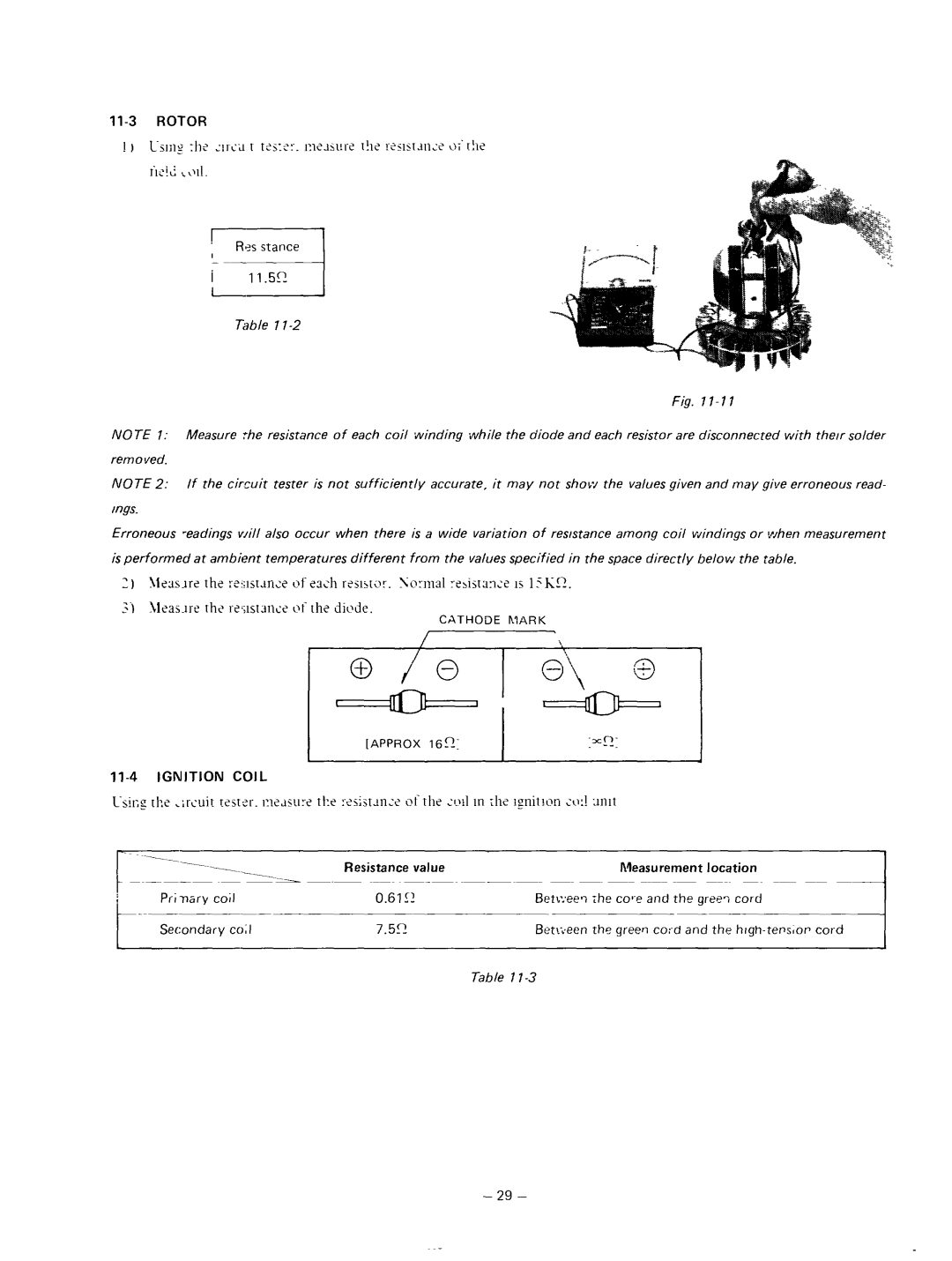
NOTE 1: Measure the resistance of each coil winding while the diode and each resistor are disconnected with the/r solder removed.
NOTE 2: If the circuit tester is not sufficiently accurate, it may not show the values given and may give erroneous read- mngs.
Erroneous
is performed at ambient temperatures different from the values specified in the space directly below the table.
[APPROX | 162: | I |
11-4 IGNITION COIL
Resistance value |
|
| Measurement | location |
| |||
0.61’1 | B~tl::ee? | The | and | the gree? | cord |
| ||
7.52 | Betkseen | the | grew | cord | and | the | cord | |
Table 7
- 29 -
