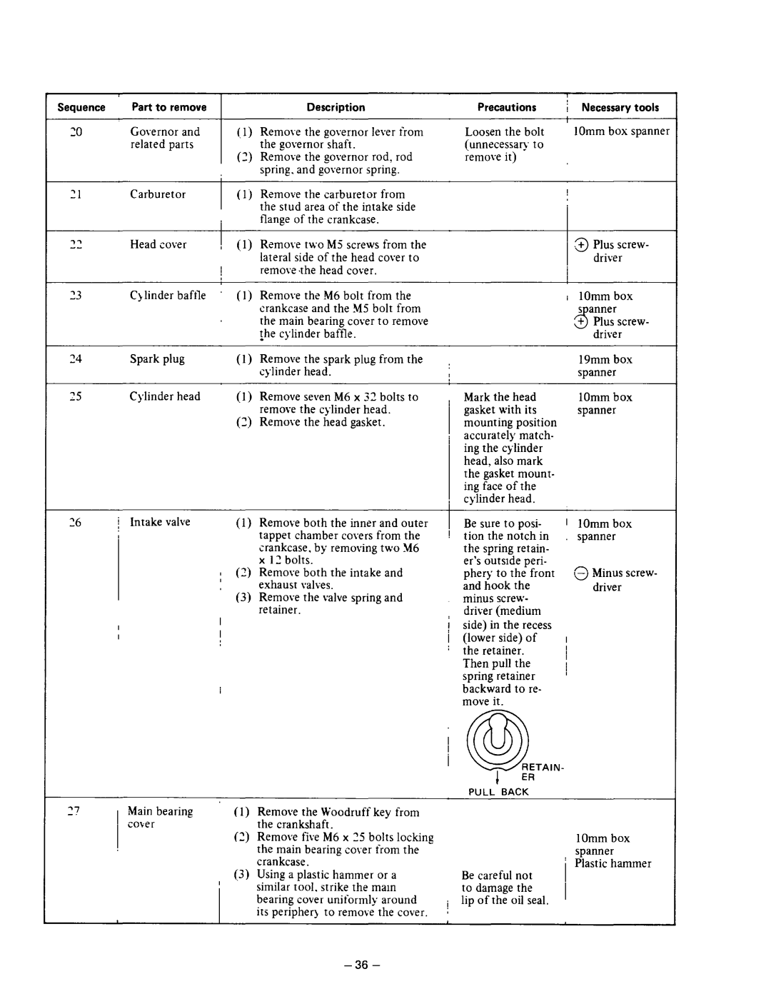
Sequence
20
‘1
33
24
25
Part to remove |
| Description | |
Governor | and | (.1) | Remove the governor lever from |
related parts |
| the governor shaft. | |
|
| (~j Remove the governor rod, rod | |
|
|
| spring. and governor spring. |
Carburetor | (1 j | Remove the carburetor from | |
|
|
| the stud area of the intake side |
|
|
| flange of the crankcase. |
Head cover | , (1 j | Remove two M5 screws from the | |
|
| I | lateral side of the head cover to |
|
| remove the head cover. | |
|
|
| |
Qlinder | baffle | (1 j | Remove the M6 bolt from the |
|
|
| crankcase and the $15 bolt from |
|
|
| the main bearing cover to remove |
|
|
| !he cylinder baffle. |
Spark plug | (1) | Remove the spark plug from the | |
|
|
| cylinder head. |
Cylinder | head | (1 j | Remove sev2nM6 x 32 bolts to |
|
|
| remove the |
|
| (3) Remove the head gasket. | |
| Precautions | / | Necessary tools | ||
| Loosen the bolt | I | 1Omm box spanner | ||
|
| ||||
| (unnecessary to |
|
|
| |
| remove it) |
|
|
|
|
|
|
| I |
|
|
|
|
|
| .B | Plus screw- |
|
|
|
|
| driver |
|
|
| i | 1Omm box | |
|
|
|
| 5 anner | |
|
|
|
| 5+ | Plus screw- |
|
|
|
|
| driver |
: |
|
|
| 19mm box | |
|
|
|
| spanner | |
; | Mark the head |
| 1Omm box | ||
| gasket with its |
| spanner | ||
| mounting | position |
|
|
|
| accurately | match- |
|
|
|
| ing the cylinder |
|
|
| |
| head, also mark |
|
|
| |
| the gasket mount- |
|
|
| |
| ing face of the |
|
|
| |
, | cylinder head. |
|
|
| |
i Intake valve | (1) Remove both the inner and outer |
| tappet chamber covers from the |
| crankcase. by removing two Y6 |
| x 1: bolts. |
| : (3) Remove both the intake and |
| exhaust valves. |
| (3) Remove the valve spring and |
| retainer. |
| I |
| I |
(1)Remove the Woodruff key from the crankshaft.
(2)Remove five M6 x 15 bolts locking the main bearing cover from the crankcase.
(3)Using a plastic hammer or a similar tool. strike the mam bearing cover uniformly around its peripheq to
B2 sure to posi- tion the notch in the spring retain- er’s outside peri- phery to the front and hook the minus screw-
i driver (medium side) in the recess
/(lower side) of a the retainer.
Then pull the spring retainer backward to re- move it.
I@RETAIN-
1ER
PULL BACK
Be careful not to damage the
ilip of the oil seal.
;
t1Omm box spanner
13Minus screw- driver
I
I
’
1Omm box spanner
