8-2-3 DC OUTPUT
DC output is taken out from the main coil and is fed to the diode at which time the output undergoes
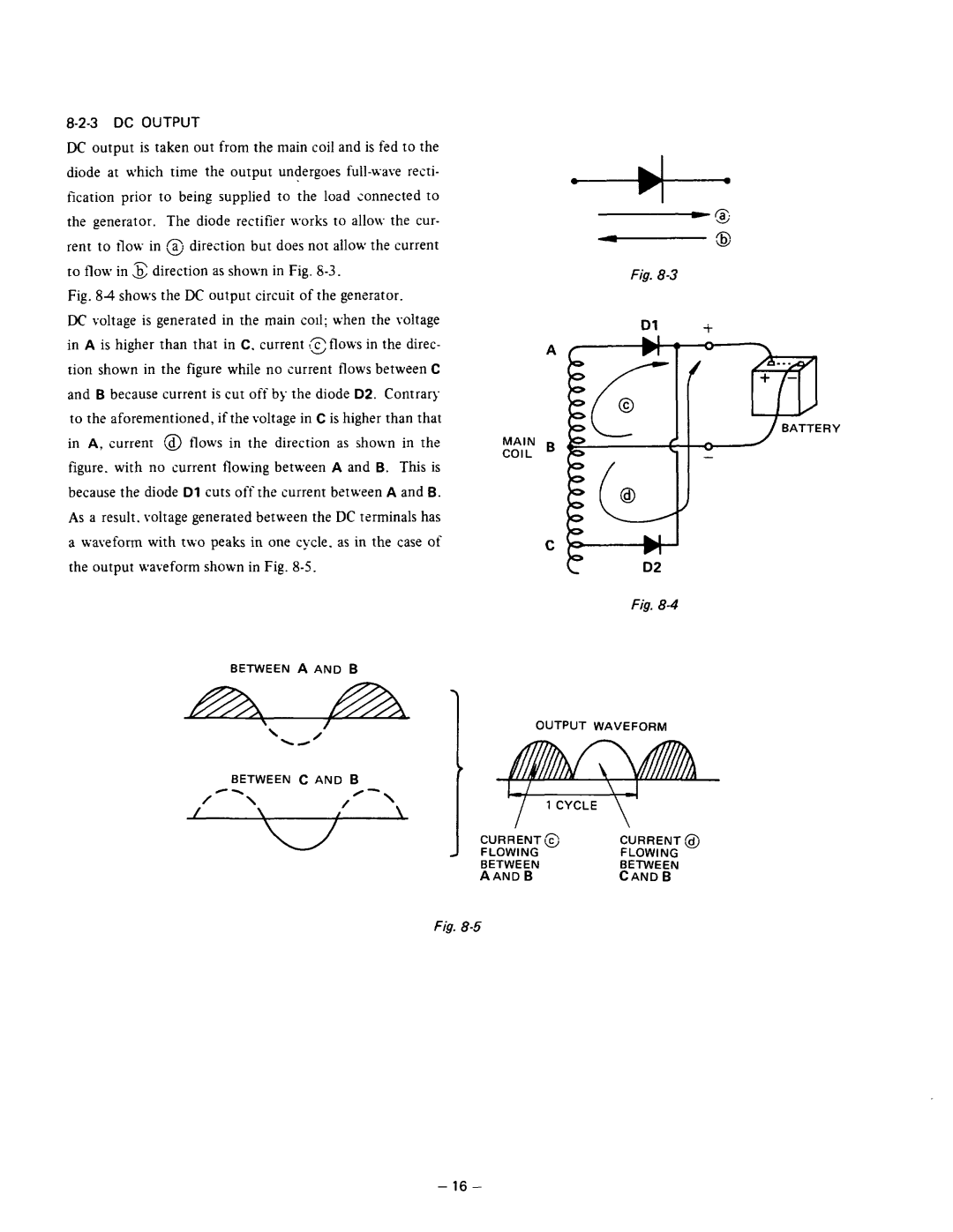
Fig. 84 shows the DC output circuit of the generator.
DC voltage is generated in the main coil; when the voltage in A is higher than that in C. current !~flows in the direc- tion shown in the figure while no current flows between C and B because current is cut off by the diode D2. Contraq to the aforementioned, if the voltage in C is higher than that in A, current a flows in the direction as sholvn in the figure. with no current flowing between A and B. This is because the diode Dl cuts off the current between A and B. As a result. voltage generated between the DC terminals has a waveform with t\vo peaks in one cycle. as in the case of the output waveform shown in Fig.
Fig.
Dl +
MAIN B
COIL
Fig.
BETWEEN A AND B
OUTPUT WAVEFORM
BETWEEN C AND B
=w= | CURRENT 0 | CURRENT @ | |
FLOWING | FLOWING | ||
| |||
| BETWEEN | BETWEEN | |
| AAND B | CAND B |
Fig.
- 16 -