STATOR |
|
|
|
|
|
|
|
|
|
|
|
| ||
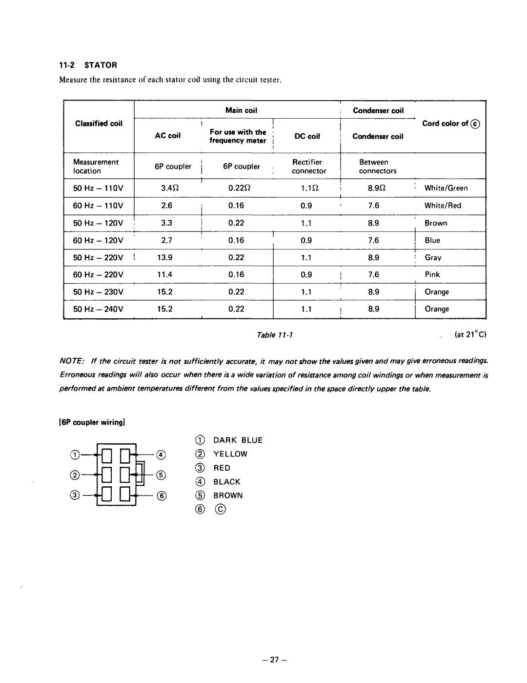
Measure the resistance of each stator coil using the circuit tester. |
|
|
|
|
| |||||||||
|
|
|
|
|
|
|
|
|
|
| I |
|
|
|
|
|
|
|
|
|
| Main | coil |
|
| : | Condenser | coil |
|
Classified | coil |
|
|
| ! |
|
| I |
|
|
| I | Cord color of @ | |
|
|
|
|
|
| I |
|
| ||||||
|
|
|
| AC | coil | For | use with the I |
|
|
|
| |||
|
|
|
| DC coil | : | Condenser | coil |
| ||||||
|
|
|
| frequency | meter | / |
| |||||||
|
|
|
|
|
|
|
|
|
|
| ||||
|
|
|
|
|
|
|
|
|
|
| I |
|
|
|
Measurement |
| 6P | coupler | j | 6P coupler |
| Rectifier | 1 | Between |
|
| |||
location |
|
|
| connector | j | connectors |
|
| ||||||
|
|
|
|
|
|
|
|
|
| |||||
|
|
|
|
|
|
|
|
|
|
| I |
|
|
|
|
| 3.4R | ’ | 0.2251 |
| 1.1n | I | 8.9R | : | White/Green | ||||
|
|
|
|
|
|
|
|
|
|
| I |
|
|
|
|
| 2.6 | I | 0.16 |
|
| 0.9 | : | 7.6 |
| White/Red | |||
|
|
|
|
|
|
|
|
|
|
|
|
|
| |
| j | 3.3 | j | 0.22 |
|
| 1.1 |
| 8.9 | I | Brown | |||
|
|
|
|
|
|
|
|
| I |
|
|
|
| |
|
| 2.7 | ’ | 0.16 |
| 0.9 |
| 7.6 | 1 | Blue | ||||
|
|
| , |
| ||||||||||
|
|
|
|
|
|
|
|
|
|
|
|
| I |
|
50 | Hz - | 220V | ! | 13.9 |
| 0.22 |
|
| 1.1 |
| 8.9 | : | Gray | |
60 | Hz - | 220V |
| 11.4 |
| 0.16 |
| , | 0.9 | i | 7.6 |
| Pink | |
50 | Hz - | 230V |
| 15.2 |
| 0.22 |
|
| 1.1 |
| 8.9 | i | Orange | |
50 | Hz - | 240V |
| 15.2 | I | 0.22 |
|
| 1.1 | j | 8.9 |
| Orange | |
|
|
|
|
|
|
|
|
|
|
|
|
|
| |
|
|
|
|
|
|
|
| Table |
|
|
|
| (at 21cC) | |
NOTE: If the circuit tester is not sufficient/y accurate, it may not show the values given and may give erroneous readings. Erroneous readings will also occur when there is a wide variation of resistance among coil windings or when measurement is
performed at ambient temperatures different from the values specified in the space directly upper the table.
[6P coupler wiring]
DARK BLUE
YELLOW
RED
BLACK
BROWN
- 27 -
