Sequence 1 Part to remove
Description | Precautions | Necessary tools |
12Bas2 platz
13Recoil starter
Starter pullek
I
I
I
Fig.
(1)Remove one set screw of the earth wire which grounds the rear housing and base plate togethsr (Zr)OV system onlv).
(2)Rsmove four 5115x 10 bolts from under the base plate.
(1)Remove the recoil starter from the rear housing. by removing three 516 x 8 flange bolts.
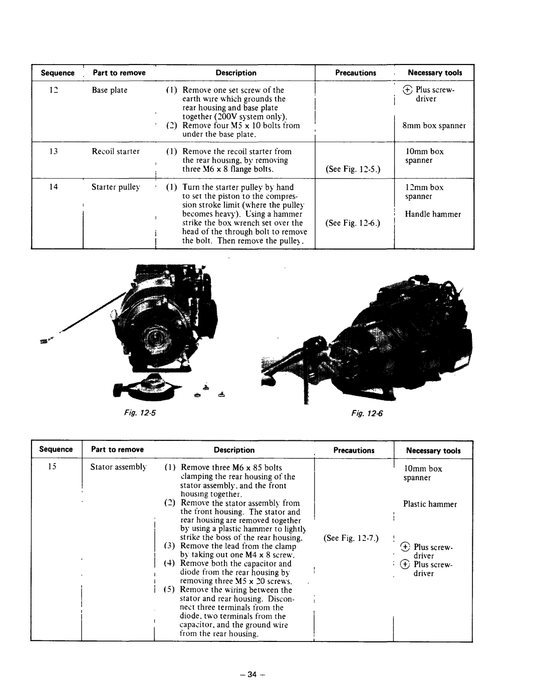
(1 j Turn the starter pulley b]- hand to set the piston to the compres- sion stroke limit (lvhere the pulle) becomes heavy). Csing a hammer strike the box wrench set ov2r the head of the through bolt to remove the bolt. Then remove the pulleb _
; | T Plus screw- | |
u | driver | |
I |
| |
|
| |
I | Smm box spanner | |
j | ||
1Omm box spanner
(See Fig. 12-S.)
1?mm box spanner
Handle hammer
(See Fig. 1Z-6.)
Fig.
Sequence | Part to remove | Description |
15Stator assemblq- (1 j Remove three M6 x 85 bolts clamping the rear housing of the stator assembly. and the front housing together.
(2j Remove the stator
(3)Remove the lead from the clamp
b_~taking- out one M4 x 8 scre\v.
I ...
1 (4) Kemove both the capacitor and
Idiode from the rear housing by
I removing three M5 x 30 scre\\s. / (5) Remove the wiring between the stator and rear housing. Discon-
nest three terminals irom the diode. t\vo terminals from the capacitor. and the ground \vire from the r2ar housing.
Precautions | , | Necessary tools |
| I |
|
| ’ | 1Omm box |
| spanner | |
| Plastic hammer | |
(See Fig. | j |
|
| 3 | Plus screw- |
| _ driver | |
I | : Cd Plus screw- | |
driver | ||
| ||
i |
|
