Sun Microsystems 2500 manual To cable a 1x3 array configuration for maximum redundancy

Models: 2500

1 128
Download 128 pages 5.11 Kb
Page 62
Image 62

and two expansion trays. The cable connections on the
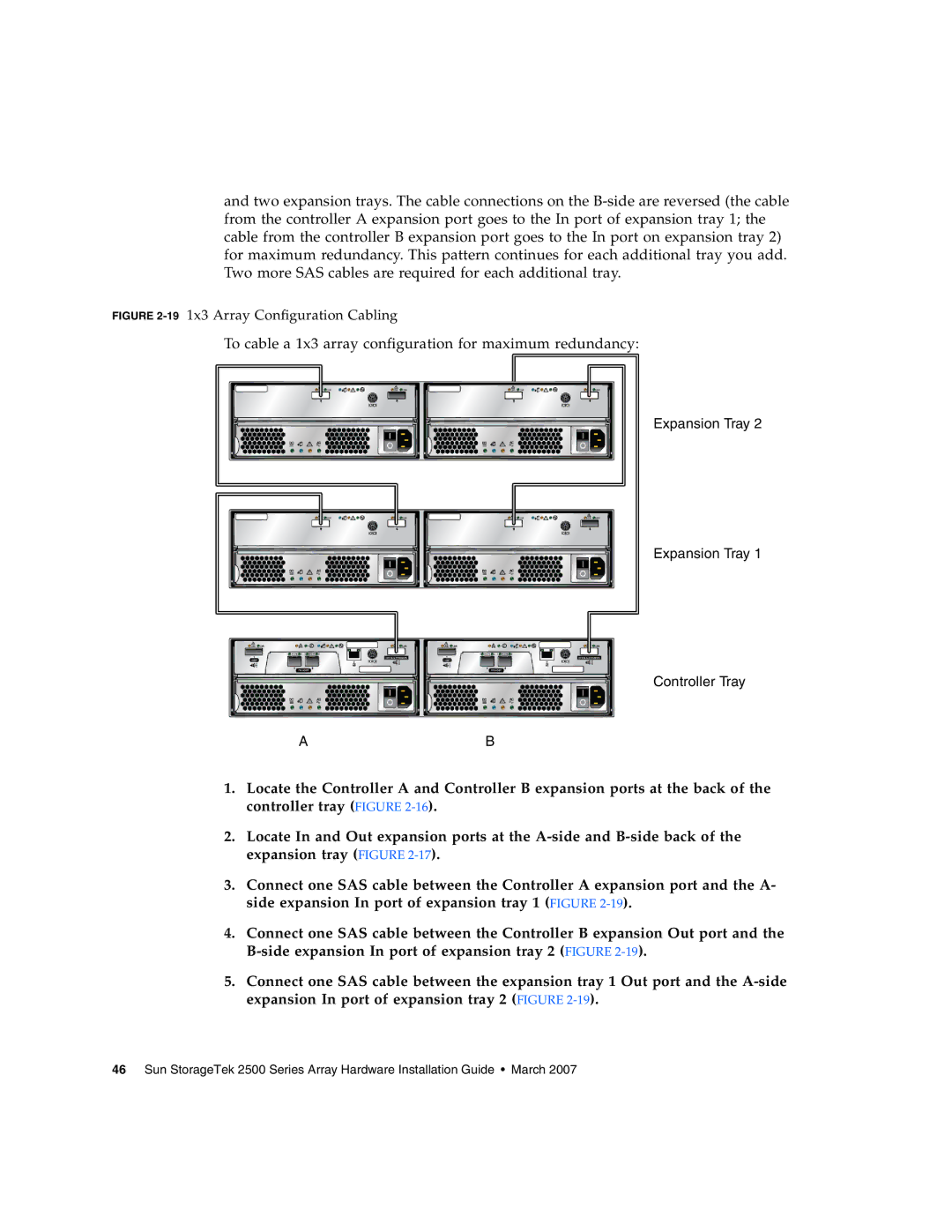
 B-side are reversed (the cable from the controller A expansion port goes to the In port of expansion tray 1; the cable from the controller B expansion port goes to the In port on expansion tray 2) for maximum redundancy. This pattern continues for each additional tray you add. Two more SAS cables are required for each additional tray.

FIGURE 2-191x3 Array Configuration Cabling

To cable a 1x3 array configuration for maximum redundancy:

Expansion Tray 2

Expansion Tray 1

Controller Tray

AB

1.Locate the Controller A and Controller B expansion ports at the back of the controller tray (FIGURE 2-16).

2.Locate In and Out expansion ports at the A-side and B-side back of the expansion tray (FIGURE 2-17).

3.Connect one SAS cable between the Controller A expansion port and the A- side expansion In port of expansion tray 1 (FIGURE 2-19).

4.Connect one SAS cable between the Controller B expansion Out port and the B-side expansion In port of expansion tray 2 (FIGURE 2-19).

5.Connect one SAS cable between the expansion tray 1 Out port and the A-side expansion In port of expansion tray 2 (FIGURE 2-19).

46 Sun StorageTek 2500 Series Array Hardware Installation Guide • March 2007

Page 62
Image 62
Sun Microsystems 2500 manual To cable a 1x3 array configuration for maximum redundancy