To connect a terminal to the serial port of a controller:

1.Connect the 6-pin mini-DIN connector of the serial cable to the serial port connector (diagnostic port) on the controller (FIGURE 1-3on page 6).

2.Connect the RJ-45 connector of the serial cable to the serial port connector on the terminal. It may be necessary to use an RJ45-DB9 adapter between the serial cable RJ-45 connector and the serial port of the terminal.

3.For PC and laptop serial connections, you will also need to use a null modem. Connect the null modem between the serial cable or RJ45-DB9 adapter and the PC serial port.

Note – If your PC does not have a serial port, you can use a USB–Serial Port adapter (separately available from third-party vendors; not included with 2500 Series Array ship kits).

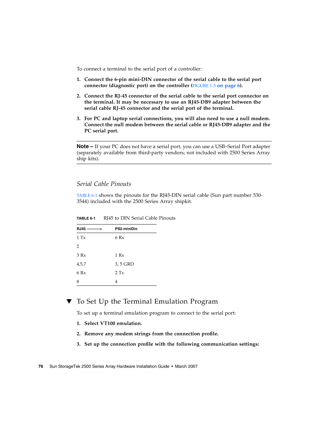
Serial Cable Pinouts

TABLE 6-1shows the pinouts for the RJ45-DIN serial cable (Sun part number 530- 3544) included with the 2500 Series Array shipkit.

TABLE 6-1RJ45 to DIN Serial Cable Pinouts

RJ45 ---------->

PS2-miniDin


1 Tx

6 Rx

2


3 Rx

1 Rx

4,5,7

3, 5 GRD

6 Rx

2 Tx

8

4


To Set Up the Terminal Emulation Program

To set up a terminal emulation program to connect to the serial port:

1.Select VT100 emulation.

2.Remove any modem strings from the connection profile.

3.Set up the connection profile with the following communication settings:

76 Sun StorageTek 2500 Series Array Hardware Installation Guide • March 2007
Page 92
Image 92
Sun Microsystems 2500 manual To Set Up the Terminal Emulation Program