|
|
|
|
|
|
|
| Chapter 1: Introduction |
|
|
|
|
|
| |||
|
|
|
|
|
| |||
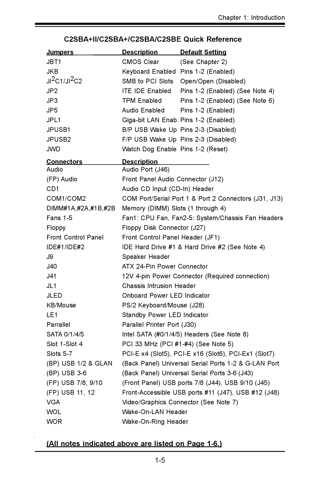
C2SBA+II/C2SBA+/C2SBA/C2SBE Quick Reference | ||||||||
Jumpers |
| Description | Default Setting | |||||
|
|
|
|
|
|
| ||
JBT1 |
| CMOS Clear | (See Chapter 2) | |||||
JKB | Keyboard Enabled | Pins | (Enabled) | |||||
JI2C1/JI2C2 | SMB to PCI Slots | Open/Open (Disabled) | ||||||
JP2 | ITE IDE Enabled | Pins | (Enabled) (See Note 4) | |||||
JP3 | TPM Enabled | Pins | (Enabled) (See Note 6) | |||||
JP5 | Audio Enabled | Pins | (Enabled) | |||||
JPL1 | (Enabled) | |||||||
JPUSB1 | B/P USB Wake Up Pins | (Disabled) | ||||||
JPUSB2 | F/P USB Wake Up Pins | (Disabled) | ||||||
JWD | Watch Dog Enable Pins | (Reset) | ||||||
Connectors |
| Description |
|
|
|
|
| |
Audio | Audio Port (J46) |
|
|
|
| |||
(FP) Audio | Front Panel Audio Connector (J12) | |||||||
CD1 | Audio CD Input | |||||||
COM1/COM2 | COM Port/Serial Port 1 & Port 2 Connectors (J31, J13) | |||||||
DIMM#1A,#2A,#1B,#2B | Memory (DIMM) Slots (1 through 4) | |||||||
Fans | Fan1: CPU Fan, | |||||||
Floppy | Floppy Disk Connector (J27) |
|
| |||||
Front Control Panel | Front Control Panel Header (JF1) | |||||||
IDE#1/IDE#2 | IDE Hard Drive #1 & Hard Drive #2 (See Note 4) | |||||||
J9 | Speaker Header |
|
|
|
| |||
J40 | ATX | |||||||
J41 | 12V | |||||||
JL1 | Chassis Intrusion Header |
|
| |||||
JLED | Onboard Power LED Indicator | |||||||
KB/Mouse | PS/2 Keyboard/Mouse (J28) |
|
| |||||
LE1 | Standby Power LED Indicator | |||||||
Parrallel | Parallel Printer Port (J30) |
|
| |||||
SATA 0/1/4/5 | Intel SATA (#0/1/4/5) Headers (See Note 8) | |||||||
Slot | PCI 33 MHz (PCI | |||||||
Slots | ||||||||
(BP) USB 1/2 & GLAN | (Back Panel) Universal Serial Ports | |||||||
(BP) USB | (Back Panel) Universal Serial Ports | |||||||
(FP) USB 7/8, 9/10 | (Front Panel) USB ports 7/8 (J44), USB 9/10 (J45) | |||||||
(FP) USB 11, 12 | ||||||||
VGA | Video/Graphics Connector (See Note 7) | |||||||
WOL |
|
| ||||||
WOR |
|
| ||||||