Chapter 2: Installation
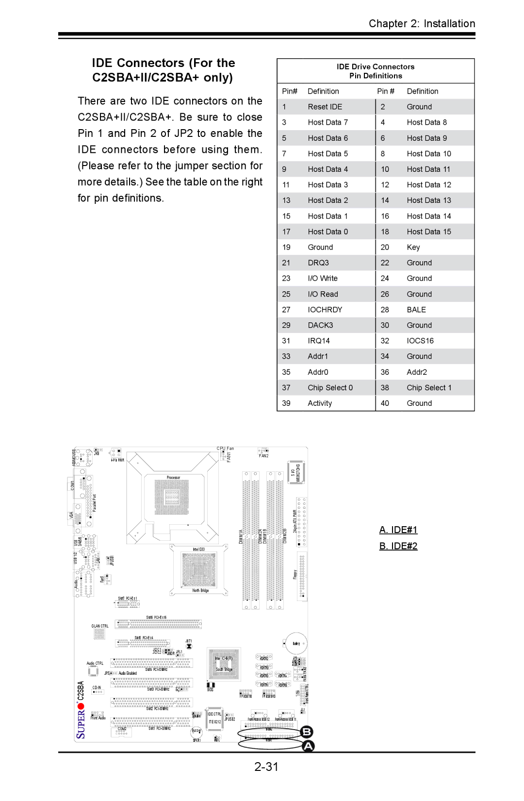
IDE Connectors (For the C2SBA+II/C2SBA+ only)
IDE Drive Connectors
Pin Definitions
There are two IDE connectors on the C2SBA+II/C2SBA+. Be sure to close Pin 1 and Pin 2 of JP2 to enable the IDE connectors before using them. (Please refer to the jumper section for more details.) See the table on the right for pin definitions.
Pin# Definition
1Reset IDE
3Host Data 7
5Host Data 6
7Host Data 5
9Host Data 4
11Host Data 3
13Host Data 2
15Host Data 1
17Host Data 0
19Ground
21DRQ3
23I/O Write
25I/O Read
27IOCHRDY
29DACK3
31IRQ14
33Addr1
35Addr0
37Chip Select 0
39Activity
Pin # Definition
2 Ground
4Host Data 8
6Host Data 9
8Host Data 10
10Host Data 11
12Host Data 12
14Host Data 13
16Host Data 14
18Host Data 15
20Key
22Ground
24Ground
26Ground
28BALE
30Ground
32IOCS16
34Ground
36Addr2
38Chip Select 1
40Ground
KB/MOUSE | JKB |
COM1 |
|
VGA | Parallel Port |
| |
USB 3/4/5/6 |
|
USB 1/2 | LAN |
| CPU Fan |
FAN1 | |
| Processor |
| DIMM1A |
| Intel G33 |
![]()
![]() JPUSB1
JPUSB1
Audio | Fan5 |
| North Bridge |
| Slot7 |
FAN2
DIMM2A DIMM1B
| S I/O W83627DHG |
DIMM2B | |
| Floppy |
A.IDE#1
B.IDE#2
C2SBA
| Slot6 |
|
|
GLAN CTRL |
|
|
|
| Slot5 |
| JBT1 |
|
|
| |
| JI2C1 | JWOR | JPL1 |
| JI2C2 | ||
Audio CTRL |
|
|
|
JP5 | Slot4 |
|
|
Audio Enabled |
|
| |
Slot3 | JP2 | ||
Intel ICH9(R)
South Bridge
BIOS
|
|
| Battery |
|
|
| JP3 |
| |
|
|
| JWD |
|
|
| JLED | FAN3 | |
|
|
| ||
|
| |||
|
| FAN4 | ||
|
|
|
| |
|
| CTRL | ||
|
|
| LE1 | |
FP USB 7/8 | FP USB 9/10 |
| Panel | |
|
| |||
|
|
|
| Front |
| Slot2 |
|
|
Front Audio |
| Speaker | IDE CTRL |
| ITE 8212 JPUSB2 | ||
|
| ||
|
|
| |
COM2 | Slot1 | Buzzer |
|
|
|
| |
|
| SPKR1 | WOL |
| JL1 |
IDE#2 | B |
|
![]()
![]()
![]()
![]()
![]()
![]()
![]()
![]()
![]()
![]() IDE#1
IDE#1![]()
![]()
![]()
![]()
![]()
![]()
![]()
![]()
![]()
A