![]()
![]()
![]()
![]()
![]()
![]() C2SBA+II/C2SBA+/C2SBA/C2SBE User's Manual
C2SBA+II/C2SBA+/C2SBA/C2SBE User's Manual
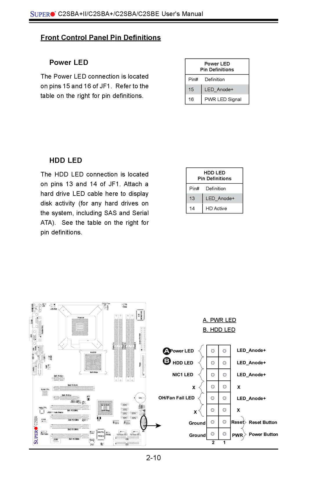
Front Control Panel Pin Definitions
Power LED
The Power LED connection is located on pins 15 and 16 of JF1. Refer to the table on the right for pin definitions.
HDD LED
The HDD LED connection is located on pins 13 and 14 of JF1. Attach a hard drive LED cable here to display disk activity (for any hard drives on the system, including SAS and Serial ATA). See the table on the right for pin definitions.
Power LED
Pin Definitions
Pin# Definition
15LED_Anode+
16PWR LED Signal
HDD LED
Pin Definitions
Pin# Definition
13LED_Anode+
14HD Active
KB/MOUSE | JKB |
| |
COM1 |
|
VGA | Parallel Port |
|
| CPU Fan |
FAN1 | |
| Processor |
FAN2
S I/O W83627DHG |
A. PWR LED B. HDD LED
USB 3/4/5/6 |
|
USB 1/2 | LAN |
DIMM1A |
Intel G33 |
![]()
![]() JPUSB1
JPUSB1
Audio | Fan5 |
| North Bridge |
| Slot7 |
DIMM2A DIMM1B
DIMM2B | 24 |
|
| Floppy |
|
|
| |
|
|
|
APower LED
BHDD LED
NIC1 LED
LED_Anode+
LED_Anode+
LED_Anode+
C2SBA
Slot6
GLAN CTRL |
|
|
|
|
|
| Slot5 |
| JBT1 |
| |
|
|
|
|
| |
|
| JI2C1 | JWOR | JPL1 |
|
|
| JI2C2 | Intel ICH9(R) | ||
Audio CTRL |
|
|
|
| |
|
|
|
|
| |
JP5 | Audio Enabled | Slot4 |
|
| South Bridge |
|
|
|
| ||
| Slot3 | JP2 | BIOS | ||
|
| Slot2 |
|
| |
Front Audio |
|
|
| Speaker | IDE CTRL |
|
|
| ITE 8212 JPUSB2 | ||
|
|
|
| ||
| COM2 | Slot1 | Buzzer |
| |
|
|
|
| SPKR1 | WOL |
|
|
| Battery |
| |
|
| JP3 |
| ||
|
|
| JWD |
| |
|
| JLED | FAN3 | ||
|
|
| |||
|
| ||||
|
| FAN4 | |||
|
|
|
| ||
|
| CTRL | |||
|
|
| LE1 | ||
FP USB 7/8 | FP USB 9/10 | Panel | |||
| |||||
|
|
|
| Front | |
|
|
|
| JL1 | |
| |||||
| IDE#2 |
|
|
| |
| IDE#1 |
|
|
| |
X
OH/Fan Fail LED
X
Ground
Ground
X
LED_Anode+
X
Reset Reset Button
PWR Power Button
2 1