![]()
![]()
![]()
![]()
![]()
![]() C2SBA+II/C2SBA+/C2SBA/C2SBE User's Manual
C2SBA+II/C2SBA+/C2SBA/C2SBE User's Manual
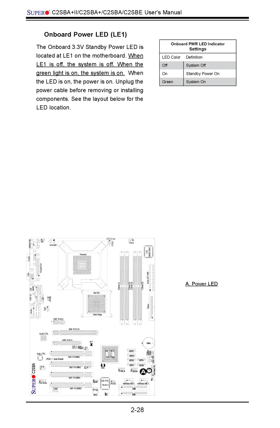
Onboard Power LED (LE1)
The Onboard 3.3V Standby Power LED is located at LE1 on the motherboard. When LE1 is off, the system is off. When the green light is on, the system is on. When the LED is on, the power is on. Unplug the power cable before removing or installing components. See the layout below for the LED location.
Onboard PWR LED Indicator
|
| Settings |
|
|
|
LED Color |
| Definition |
Off |
| System Off |
| ||
On |
| Standby Power On |
| ||
Green |
| System On |
| ||
|
|
|
KB/MOUSE | JKB |
COM1 |
|
VGA | Parallel Port |
| |
USB 3/4/5/6 |
|
USB 1/2 | LAN |
| CPU Fan |
FAN1 | |
| Processor |
| DIMM1A |
| Intel G33 |
![]()
![]() JPUSB1
JPUSB1
Audio | Fan5 |
| North Bridge |
| Slot7 |
FAN2
DIMM2A DIMM1B
| S I/O W83627DHG |
DIMM2B | |
| Floppy |
A. Power LED
C2SBA
| Slot6 |
|
|
GLAN CTRL |
|
|
|
| Slot5 |
| JBT1 |
|
|
| |
| JI2C1 | JWOR | JPL1 |
| JI2C2 | ||
Audio CTRL |
|
|
|
JP5 | Slot4 |
|
|
Audio Enabled |
|
| |
Slot3 | JP2 | ||
Intel ICH9(R)
South Bridge
BIOS
|
| Battery |
|
| JP3 |
| |
|
| JWD |
|
| JLED | FAN3 | |
|
| ||
| |||
| FAN4 | ||
|
|
| |
| Front Panel CTRL | ||
FP USB 7/8 | FP USB 9/10 | A LE1 |
| Slot2 |
|
|
Front Audio |
| Speaker | IDE CTRL |
| ITE 8212 JPUSB2 | ||
|
| ||
|
|
| |
COM2 | Slot1 | Buzzer |
|
|
| SPKR1 | WOL |
| JL1 |
IDE#2 |
|
IDE#1 |
|