BUTTONS & CONNECTIONS...continued
Back Panel
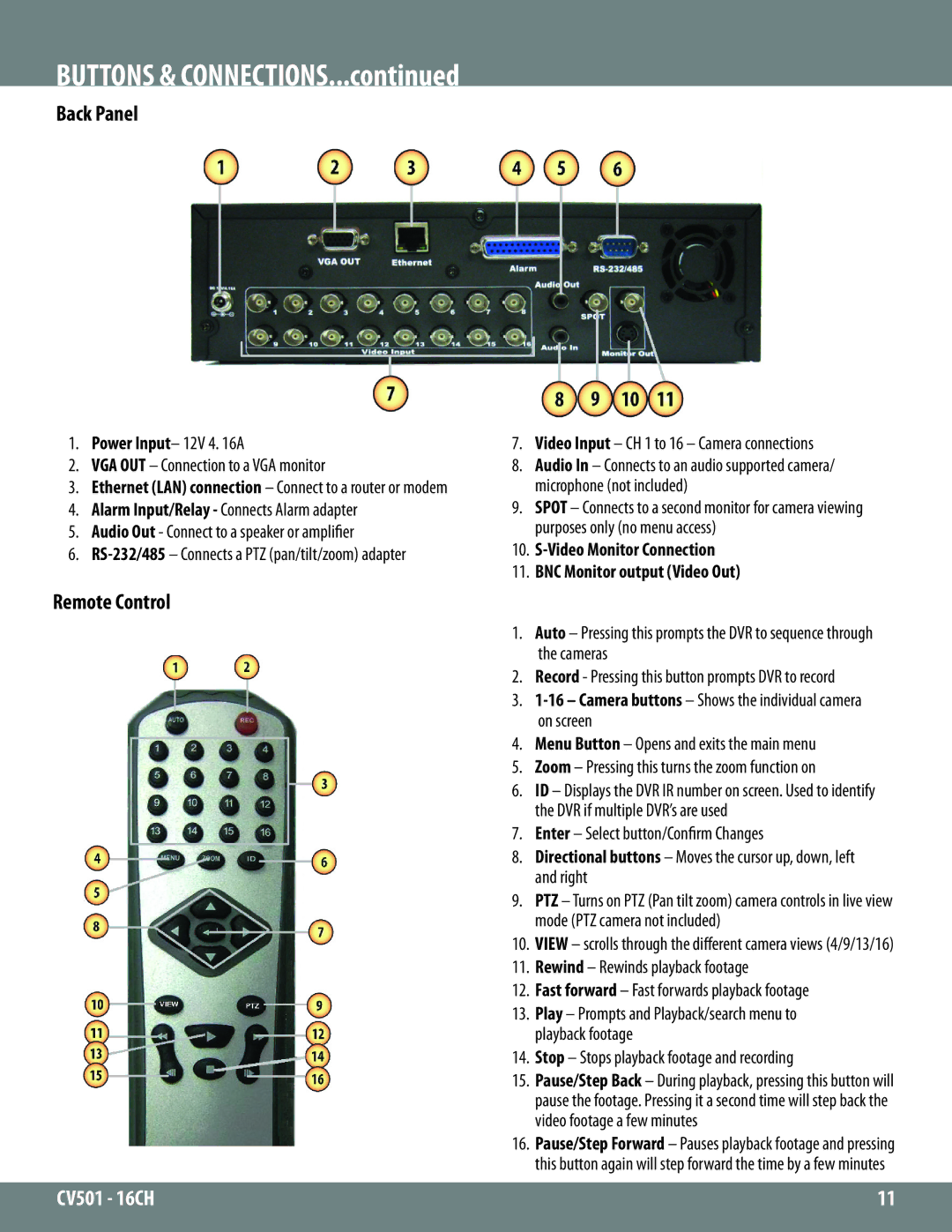
1.Power Input– 12V 4. 16A
2.VGA OUT – Connection to a VGA monitor
3.Ethernet (LAN) connection – Connect to a router or modem
4.Alarm Input/Relay - Connects Alarm adapter
5.Audio Out - Connect to a speaker or amplifier
6.
Remote Control
7.Video Input – CH 1 to 16 – Camera connections
8.Audio In – Connects to an audio supported camera/ microphone (not included)
9.SPOT – Connects to a second monitor for camera viewing purposes only (no menu access)
10.S-Video Monitor Connection
11.BNC Monitor output (Video Out)
1.Auto – Pressing this prompts the DVR to sequence through the cameras
2.Record - Pressing this button prompts DVR to record
3.
4.Menu Button – Opens and exits the main menu
5.Zoom – Pressing this turns the zoom function on
6.ID – Displays the DVR IR number on screen. Used to identify the DVR if multiple DVR’s are used
7.Enter – Select button/Confirm Changes
8.Directional buttons – Moves the cursor up, down, left and right
9.PTZ – Turns on PTZ (Pan tilt zoom) camera controls in live view mode (PTZ camera not included)
10.VIEW – scrolls through the different camera views (4/9/13/16)
11.Rewind – Rewinds playback footage
12.Fast forward – Fast forwards playback footage
13.Play – Prompts and Playback/search menu to playback footage
14.Stop – Stops playback footage and recording
15.Pause/Step Back – During playback, pressing this button will pause the footage. Pressing it a second time will step back the video footage a few minutes
16.Pause/Step Forward – Pauses playback footage and pressing this button again will step forward the time by a few minutes
CV501 - 16CH | 11 |
|
|
