Veritas Cluster Server Installation Guide
Veritas Cluster Server Installation Guide
Legal Notice
Symantec Corporation Ellis Street Mountain View, CA
Technical Support
Contacting Technical Support
Customer service
Licensing and registration
Documentation feedback
Maintenance agreement resources
Additional enterprise services
Contents
Contents
Chapter Configuring VCS clusters for data integrity
Chapter Adding and removing cluster nodes
121
171
Index 173
Contents
About Veritas Cluster Server
About VCS basics
This chapter includes the following topics
About multiple nodes
About shared storage
Example of a four-node VCS cluster
See About the LLT and GAB configuration files on
About LLT and GAB
About network channels for heartbeating
About preexisting network partitions
About VCS seeding
About VCS notifications
About VCS features
Veritas Installation Assessment Service
About global clusters
About VCS optional components
About I/O fencing
You can add the following optional components to VCS
About Symantec Product Authentication Service AT
About Cluster Manager Java Console
See Preparing to configure the clusters in secure mode on
See Installing the Java Console on
About Veritas Cluster Server Management Console
About VCS optional components
Page
About planning to install VCS
Hardware requirements
1lists the hardware requirements for a VCS cluster
Required disk space
Hardware requirements for a VCS cluster
Description
Supported operating systems
Kernel Architecture
Required Linux RPMs for VCS
Rhel
Supported software
Planning to install VCS Supported software
About preparing to install VCS
Preparing to configure the clusters in secure mode
1depicts the flow of configuring VCS cluster in secure mode
Workflow to configure VCS cluster in secure mode
Preparatory tasks to configure a cluster in secure mode
Tasks
This task
Installing the root broker for the security infrastructure
See About Symantec Product Authentication Service AT on
# ./installer
Venus # vssat showalltrustedcreds
Venus # vssat showprpl --pdrtype root \
Creating encrypted files for the security infrastructure
Venus # vssat showbrokerhash
Addprpl command
For example
RootBroker # vssat createpkg \
Performing preinstallation tasks
Obtaining VCS license keys
Task Reference
Https//licensing.symantec.com
Setting up the private network
You can use network switches instead of hubs
Page
Configuring SuSE network interfaces
See About installing and configuring VCS on
# cd /etc/sysconfig
Run the command
Where ethX is the interface name For example
# ifconfig -a
Setting up inter-system communication
# ifconfig eth0
# cd /etc/sysconfig/network
Setting up ssh on cluster systems
Accept the default location of ~/.ssh/iddsa
# ssh-keygen -t dsa
# chmod 755 ~/.ssh
Setting up shared storage
See About setting up disk-based I/O fencing on
# exec /usr/bin/ssh-agent $SHELL # ssh-add
Setting the Path variable
Setting the Manpath variable
For the C Shell csh or tcsh, type
Setting the kernel.panic tunable
Optimizing LLT media speed settings on private NICs
Case of a panic, the node will reboot after 10 seconds
Performing automated pre-installation check
Mounting the product disc
# mount -o ro /dev/cdrom /mnt/cdrom
# ./installvcs -precheck galaxy nebula
About installing and configuring VCS
VCS
To configure Veritas Cluster Server you need
Example galaxy, nebula
Example vcscluster27
To configure VCS clusters in secure mode optional, you need
To configure Smtp email notification optional, you need
Var/tmp/privatedir/roothash
To configure Snmp trap notification optional, you need
To configure global clusters optional, you need
Optional VCS RPMs
VRTSvcsmn Manual pages for VCS commands
About the VCS installation program
Optional features of the installvcs program
See About preparing to install VCS on
Installvcs command usage takes the following form
Interacting with the installvcs program
About installvcs program command options
Optional action Reference
Installvcs system1 system2... options
Option and Syntax Description
Nooptionalpkgs
Installing VCS using installonly option
Configuring VCS using configure option
3lists the installation and the configuration tasks
Installing and configuring VCS 5.0 RU3
See Configuring the basic cluster on
Overview of tasks
Starting the software installation
# ./installvcs -rsh
Specifying systems for installation
Start the installvcs program
# cd /clusterserver
Licensing VCS
See Checking licensing information on the system on
Choosing VCS RPMs for installation
Enter keys for additional product features
Choosing to install VCS RPMs or configure VCS
Starting the software configuration
See Configuring VCS using configure option on
# ./installvcs -configure
Specifying systems for configuration
Configuring the basic cluster
# cd /dvdrom/clusterserver
Page
Configuring the cluster in secure mode
Root@east.symantecexample.com
East.symantecexample.com
Symantecexample.com
Root/roothash
Adding VCS users
Configuring Smtp email notification
Enter the user’s name, password, and level of privileges
To add a user, enter y at the prompt
See Configuring Snmp trap notification on
If you do not want to add, answer n
Configuring Snmp trap notification
See Configuring global clusters on
Verify and confirm the Smtp notification information
Configuring global clusters
Verify and confirm the Snmp notification information
Installing VCS RPMs
See Creating VCS configuration files on
Creating VCS configuration files
Verifying the NIC configuration
Completing the installation
Starting VCS
Set the Persistentname for all the NICs
File description
VCS node authentication broker
Hardware requirements for the Java Console
Installing the Java Console
Software requirements for the Java Console
See Software requirements for the Java Console on
Navigate to the folder that contains the RPMs
Installing the Java Console on Linux for IBM Power
Installing the Java Console on a Windows system
# cd /mnt/cdrom/distarch/clusterserver/rpms
Installing VCS Simulator on Windows systems
Installing VCS Simulator
Installing VCS Simulator on Unix systems
Software requirements for VCS Simulator
Reviewing the installation
Verifying and updating licenses on the system
Verifying the cluster after installation
See About verifying the VCS installation on
Checking licensing information on the system
# cd /opt/VRTS/bin
Updating product licenses using vxlicinst
Replacing a VCS demo license with a permanent license
# hastop -all -force
Start VCS on each node
Accessing the VCS documentation
To access the VCS documentation
# hastart
Configuring VCS clusters for data integrity
About configuring VCS clusters for data integrity
About coordination points
About I/O fencing components
About data disks
See About data disks on
About setting up disk-based I/O fencing
1illustrates the tasks involved to configure I/O fencing
Workflow to configure disk-based I/O fencing
I/O fencing configuration files include
Preparing to configure disk-based I/O fencing
Initializing disks as VxVM disks
# fdisk -l
# vxddladm listsupport all
Libnamevidpid
Identifying disks to use as coordinator disks
Checking shared disks for I/O fencing
Example specifies the CDS format
Verifying that the nodes have access to the same disk
Testing the shared disks for SCSI-3
See Testing the disks using vxfentsthdw utility on
Testing the disks using vxfentsthdw utility
See Removing permissions for communication on
# /opt/VRTSvcs/vxfen/bin/vxfentsthdw
If you use rsh for communication
# /opt/VRTSvcs/vxfen/bin/vxfentsthdw -n
Dev/sdr
# vxdg init vxfencoorddg sdx sdy sdz
Setting up disk-based I/O fencing manually
Setting up coordinator disk groups
# vxdg -g vxfencoorddg set coordinator=on
Creating I/O fencing configuration files
For raw device configuration
Deport the coordinator disk group
Modifying VCS configuration to use I/O fencing
Make a backup copy of the main.cf file
Stop VCS on all nodes
Start VCS
Verifying I/O fencing configuration
# hacf -verify /etc/VRTSvcs/conf/config
# /etc/init.d/vxfen start
Removing permissions for communication
# vxfenadm -d
Page
About verifying the VCS installation
About the LLT and GAB configuration files
Galaxy Nebula
About the VCS configuration file main.cf
Sample main.cf file for VCS clusters
Page
Sample main.cf file for global clusters
ClusterAddress =
Gcoip requires csgnic
Wac requires gcoip
Application wac IP gcoip NIC csgnic
See Setting the Path variable on
Verifying the LLT, GAB, and VCS configuration files
Verify the content of the configuration files
Verifying LLT, GAB, and cluster operation
Output on galaxy resembles
Verifying LLT
See Verifying the cluster on
Output on nebula resembles
Eth1 UP
Verifying GAB
Output resembles
Verifying the cluster
Verifying the cluster nodes
Current
Eth1 UP eth2 UP
About adding and removing nodes
Adding a node to a cluster
Setting up the hardware
See Adding a license key on
Preparing for a manual installation when adding a node
Installing VCS RPMs for a manual installation
See Mounting the product disc on
Adding a license key
Checking licensing information on the system
SLES10/ppc64, required Rpms
See Configuring the authentication broker on node saturn on
Setting up the node to run in secure mode
See Configuring LLT and GAB on
See Setting up VCS related security configuration on
Configuring the authentication broker on node saturn
Configuring LLT and GAB
Setting up VCS related security configuration
On the new system, run the command
# /sbin/lltconfig -c
If the file on one of the existing nodes resembles
To verify GAB On the new node, run the command
Adding the node to the existing cluster
Add the new system to the cluster
Stop VCS on the new node
Removing a node from a cluster
Starting VCS and verifying the cluster
Start VCS on the new node
Verifying the status of nodes and service groups
Deleting the departing node from VCS configuration
Check the status of the systems and the service groups
# hastatus -summary
# hagrp -switch grp3 -to nebula
# hagrp -dep
# haconf -makerw # hagrp -unlink grp4 grp1
Delete the node from the cluster
Save the configuration, making it read only
Check the status
# hagrp -delete grp4
Modifying configuration files on each remaining node
Removing security credentials from the leaving node
# /etc/init.d/gab stop # /etc/init.d/llt stop
Stop GAB and LLT
To determine the RPMs to remove, enter
# rpm -qa grep Vrts
Remove the LLT and GAB configuration files
# rm /etc/llttab # rm /etc/gabtab # rm /etc/llthosts
About installing VCS on a single node
Creating a single-node cluster using the installer program
Tasks to create a single-node cluster using the installer
Preparing for a single node installation
Starting the installer for the single node cluster
See Starting the software installation on
See Licensing VCS on
Installing the VCS software manually on a single node
Creating a single-node cluster manually
Set the path variable
Verifying single-node operation
Renaming the LLT and GAB startup files
Modifying the startup files
# hastart -onenode
Adding a node to a single-node cluster
Setting up a node to join the single-node cluster
Installing VxVM or VxFS if necessary
Display the service groups currently configured
Configuring the shared storage
See Setting up shared storage on
Bringing up the existing node
Stop VCS on Node a
Configuring LLT
Freeze the service groups
Rename the GAB and LLT startup files so they can be used
LLT directives
Setting up /etc/llthosts
Setting up /etc/llttab
See LLT directives on
Additional considerations for LLT
LLT directives
Directive Description
Reconfigure VCS on the existing nodes
Configuring GAB when adding a node to a single node cluster
Reconfiguring VCS on the existing node
Starting LLT and GAB
Verifying configuration on both nodes
Start the VCS on Node B
Unfreeze the service groups
Implement the new two-node configuration
Verify that VCS is up on both nodes
Page
About the uninstallvcs program
Preparing to uninstall VCS
See About adding and removing nodes on
Uninstalling VCS 5.0 RU3
# cd /opt/VRTS/install # ./uninstallvcs
Removing VCS 5.0 RU3 RPMs
Running uninstallvcs from the VCS 5.0 RU3 disc
Uninstallvcs program is not available in /opt/VRTS/install
Configuring LLT over UDP
Using the UDP layer for LLT
When to use LLT over UDP
Following checklist is to configure LLT over UDP
Broadcast address in the /etc/llttab file
Link command in the /etc/llttab file
See Sample configuration links crossing IP routers on
See Broadcast address in the /etc/llttab file on
Set-addr command in the /etc/llttab file
Table A-2describes the fields of the set-addr command
Configuring the netmask for LLT
Selecting UDP ports
# setparms ipaddress
For second network interface
Configuring the broadcast address for LLT
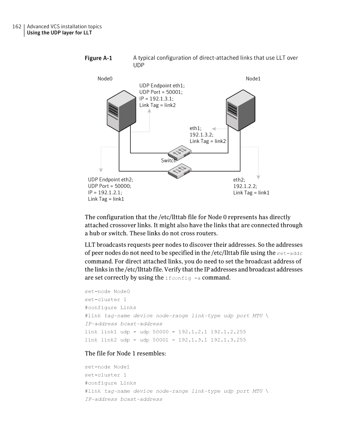
Sample configuration direct-attached links
# cat /etc/llttab
UDP
File for Node 1 resembles
Sample configuration links crossing IP routers
Figure A-2
Performing automated VCS installations
/etc/llttab file on Node 0 resembles
Or, in the case of an integer value
Syntax in the response file
Example response file
Or, in the case of a list
Response file variable definitions
Table A-3 Response file variables Variable Description
$CPICFGOPTLICENSE
$CPICFGOPTPKGPATH
$CPICFGKEYS
Table A-3
See Installing and configuring VCS 5.0 RU3 on
$CPICFGOPTUNINSTALL
# ./installvcs -responsefile /tmp/installvcs-uui.response
Index
GAB
RAM
VCS