Section 9.4 - Other DTRS control functions
which typically begins recording a few frames after the command is received from the editor (the
1)From menu group 6, move the cursor to Rec Dly ( recording delay), and press SELECT:
R e c o r d D e l a y |
|
M a c h i n e | 1 |
A u t o ( 3 F r a m e )
2)Use the UP and DOWN keys to select a value from between 0 and 9 frames, or Auto. The value of the Auto setting depends on the emulation selected (see 9.4.5, “Device emulation”) as shown below:
Emulation Frames
TASCAM 0
NOTE
See section 11.1.3 of the
9.4.7 Fast wind speed
98When a controller locates on a slave device, there are two ways in which this is achieved: a “locate” command, and a series of fast wind and shuttle commands.
To determine which command is used by your controller, and for further details regarding this function, follow the instructions in section 11.1.5 of the
The high (100 x) wind speed of the
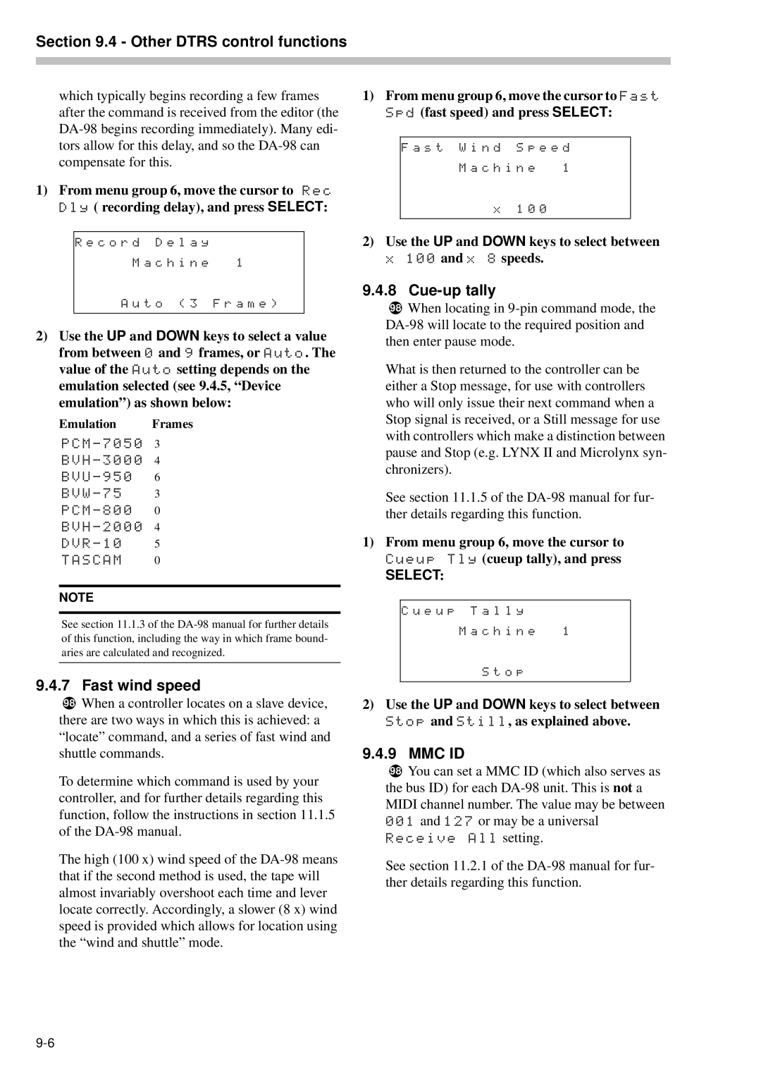
1)From menu group 6, move the cursor to Fast Spd (fast speed) and press SELECT:
F a s t W i n d | S p e e d | |
M a c h i n e | 1 | |
x | 1 0 | 0 |
|
|
|
2)Use the UP and DOWN keys to select between x 100 and x 8 speeds.
9.4.8 Cue-up tally
98When locating in
What is then returned to the controller can be either a Stop message, for use with controllers who will only issue their next command when a Stop signal is received, or a Still message for use with controllers which make a distinction between pause and Stop (e.g. LYNX II and Microlynx syn- chronizers).
See section 11.1.5 of the
1)From menu group 6, move the cursor to Cueup Tly (cueup tally), and press
SELECT:
C u e u p T a l l y
M a c h i n e 1
S t o p
2)Use the UP and DOWN keys to select between Stop and Still, as explained above.
9.4.9 MMC ID
98You can set a MMC ID (which also serves as the bus ID) for each
Receive All setting.
See section 11.2.1 of the