Section 3.2 - Connections (parallel units)
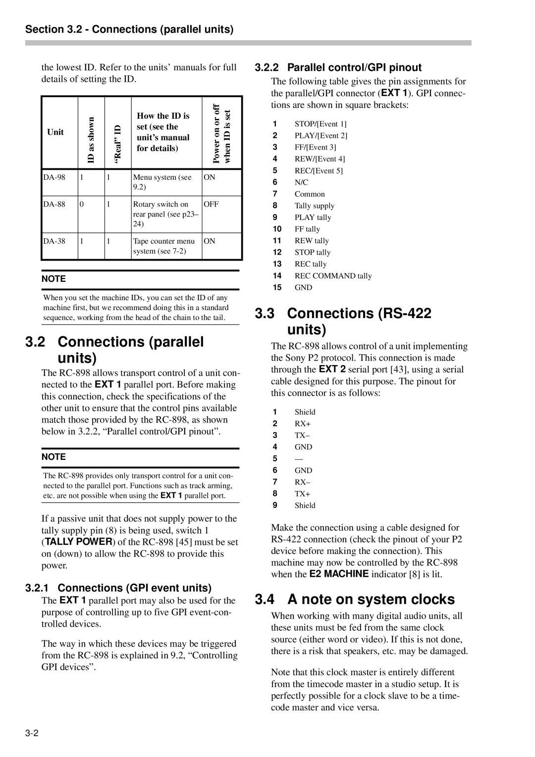
the lowest ID. Refer to the units’ manuals for full details of setting the ID.
|
|
| How the ID is |
|
|
Unit |
|
| set (see the |
|
|
|
| unit’s manual |
|
| |
|
|
|
|
| |
|
|
| for details) |
|
|
|
|
|
|
|
|
1 | 1 | Menu system (see | ON | ||
|
|
| 9.2) |
|
|
|
|
|
|
|
|
0 | 1 | Rotary switch on | OFF | ||
|
|
| rear panel (see p23– |
|
|
|
|
| 24) |
|
|
|
|
|
|
|
|
1 | 1 | Tape counter menu | ON | ||
|
|
| system (see |
|
|
|
|
|
|
|
|
|
|
|
|
|
|
NOTE
When you set the machine IDs, you can set the ID of any machine first, but we recommend doing this in a standard sequence, working from the head of the chain to the tail.
3.2 Connections (parallel units)
The
NOTE
The
If a passive unit that does not supply power to the tally supply pin (8) is being used, switch 1 (TALLY POWER) of the
3.2.1 Connections (GPI event units)
The EXT 1 parallel port may also be used for the purpose of controlling up to five GPI
The way in which these devices may be triggered from the
3.2.2 Parallel control/GPI pinout
The following table gives the pin assignments for the parallel/GPI connector (EXT 1). GPI connec- tions are shown in square brackets:
1STOP/[Event 1]
2PLAY/[Event 2]
3FF/[Event 3]
4REW/[Event 4]
5REC/[Event 5]
6N/C
7Common
8Tally supply
9PLAY tally
10FF tally
11REW tally
12STOP tally
13REC tally
14REC COMMAND tally
15GND
3.3Connections (RS-422
units)
The
1Shield
2RX+
3TX–
4GND
5—
6GND
7RX–
8TX+
9Shield
Make the connection using a cable designed for
3.4 A note on system clocks
When working with many digital audio units, all these units must be fed from the same clock source (either word or video). If this is not done, there is a risk that speakers, etc. may be damaged.
Note that this clock master is entirely different from the timecode master in a studio setup. It is perfectly possible for a clock slave to be a time- code master and vice versa.