Section 9.3 - Controlling the serial port (9-pin)
•Enter the starting memory number of your “block” minus one in the MEMORY NO. display.
•While playing back the program material which will be used with the GPI events, use the CUE STR key [39] to add repeated cue points to the list, as described in 6.5.8, “Repeated entry of location points”.
•Alternatively, key in these cue points manually from a cue list.
•Adjust the fine timing of these trigger points using the jog dial, if necessary.
Of course, there is nothing to prevent you from using existing location memories for GPI triggers, but you may find it easier to work with a series of events dedicated to this purpose.
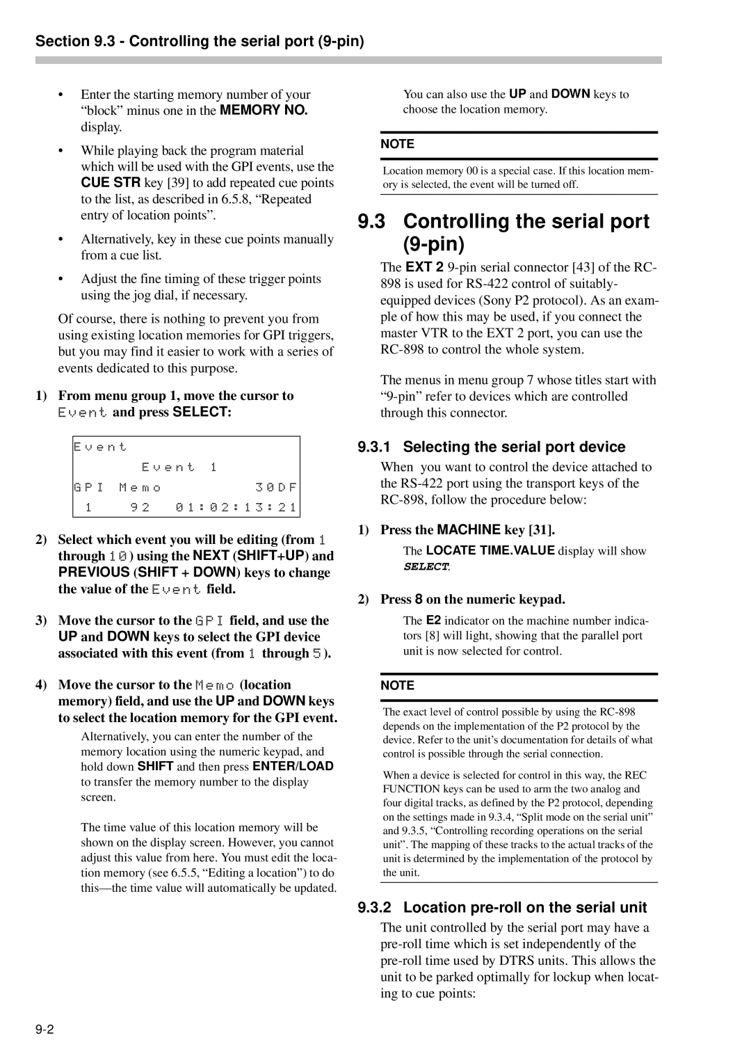
1)From menu group 1, move the cursor to Event and press SELECT:
E v e n t |
|
|
| E v e n t | 1 |
G P I M e m o | 3 0 D F | |
1 | 9 2 0 1 : 0 2 : 1 3 : 2 1 | |
|
|
|
2)Select which event you will be editing (from 1 through 10) using the NEXT (SHIFT+UP) and
PREVIOUS (SHIFT + DOWN) keys to change the value of the Event field.
3)Move the cursor to the GPI field, and use the
UP and DOWN keys to select the GPI device associated with this event (from 1 through 5).
4)Move the cursor to the Memo (location memory) field, and use the UP and DOWN keys to select the location memory for the GPI event.
Alternatively, you can enter the number of the memory location using the numeric keypad, and hold down SHIFT and then press ENTER/LOAD to transfer the memory number to the display screen.
The time value of this location memory will be shown on the display screen. However, you cannot adjust this value from here. You must edit the loca- tion memory (see 6.5.5, “Editing a location”) to do
You can also use the UP and DOWN keys to choose the location memory.
NOTE
Location memory 00 is a special case. If this location mem- ory is selected, the event will be turned off.
9.3 Controlling the serial port (9-pin)
The EXT 2
The menus in menu group 7 whose titles start with
9.3.1 Selecting the serial port device
When you want to control the device attached to the
1) Press the MACHINE key [31].
The LOCATE TIME.VALUE display will show
SELECT.
2) Press 8 on the numeric keypad.
The E2 indicator on the machine number indica- tors [8] will light, showing that the parallel port unit is now selected for control.
NOTE
The exact level of control possible by using the
When a device is selected for control in this way, the REC FUNCTION keys can be used to arm the two analog and four digital tracks, as defined by the P2 protocol, depending on the settings made in 9.3.4, “Split mode on the serial unit” and 9.3.5, “Controlling recording operations on the serial unit”. The mapping of these tracks to the actual tracks of the unit is determined by the implementation of the protocol by the unit.
9.3.2 Location pre-roll on the serial unit
The unit controlled by the serial port may have a