Section 3.1 - Connection to DTRS units

3 – Connections

This section describes not only the connection of the RC-898 to other equipment, but also provides some information on setting up a digital audio system using the RC-898.

WARNING

All connections to the RC-898 should be made with the power to all units turned off. If this is not done, the opera- tion of the units may become unstable, and damage may possibly occur.

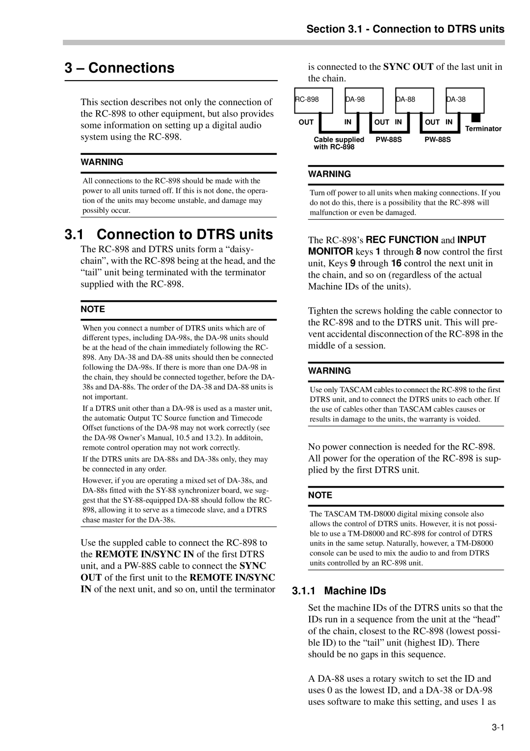
is connected to the SYNC OUT of the last unit in the chain.

RC-898

DA-98

DA-88

DA-38

OUT

IN

OUT

IN

OUT

IN


Terminator

Cable supplied PW-88S

PW-88S

with RC-898


WARNING

Turn off power to all units when making connections. If you do not do this, there is a possibility that the RC-898 will malfunction or even be damaged.

3.1 Connection to DTRS units

The RC-898 and DTRS units form a “daisy- chain”, with the RC-898 being at the head, and the “tail” unit being terminated with the terminator supplied with the RC-898.

NOTE

When you connect a number of DTRS units which are of different types, including DA-98s, the DA-98 units should be at the head of the chain immediately following the RC-

898.Any DA-38 and DA-88 units should then be connected following the DA-98s. If there is more than one DA-98 in the chain, they should be connected together, before the DA- 38s and DA-88s. The order of the DA-38 and DA-88 units is not important.

If a DTRS unit other than a DA-98 is used as a master unit, the automatic Output TC Source function and Timecode Offset functions of the DA-98 may not work correctly (see the DA-98 Owner’s Manual, 10.5 and 13.2). In additoin, remote control operation may not work correctly.

If the DTRS units are DA-88s and DA-38s only, they may be connected in any order.

However, if you are operating a mixed set of DA-38s, and DA-88s fitted with the SY-88 synchronizer board, we sug- gest that the SY-88-equipped DA-88 should follow the RC- 898, allowing it to serve as a timecode slave, and a DTRS chase master for the DA-38s.

Use the suppled cable to connect the RC-898 to the REMOTE IN/SYNC IN of the first DTRS unit, and a PW-88S cable to connect the SYNC OUT of the first unit to the REMOTE IN/SYNC IN of the next unit, and so on, until the terminator

The RC-898’s REC FUNCTION and INPUT MONITOR keys 1 through 8 now control the first unit, Keys 9 through 16 control the next unit in the chain, and so on (regardless of the actual Machine IDs of the units).

Tighten the screws holding the cable connector to the RC-898 and to the DTRS unit. This will pre- vent accidental disconnection of the RC-898 in the middle of a session.

WARNING

Use only TASCAM cables to connect the RC-898 to the first DTRS unit, and to connect the DTRS units to each other. If the use of cables other than TASCAM cables causes or results in damage to the units, the warranty is voided.

No power connection is needed for the RC-898. All power for the operation of the RC-898 is sup- plied by the first DTRS unit.

NOTE

The TASCAM TM-D8000 digital mixing console also allows the control of DTRS units. However, it is not possi- ble to use a TM-D8000 and RC-898 for control of DTRS units in the same setup. Naturally, however, a TM-D8000 console can be used to mix the audio to and from DTRS units controlled by an RC-898 unit.

3.1.1 Machine IDs

Set the machine IDs of the DTRS units so that the IDs run in a sequence from the unit at the “head” of the chain, closest to the RC-898 (lowest possi- ble ID) to the “tail” unit (highest ID). There should be no gaps in this sequence.

A DA-88 uses a rotary switch to set the ID and uses 0 as the lowest ID, and a DA-38 or DA-98 uses software to make this setting, and uses 1 as

3-1

Page 15
Image 15
Tascam RC-898 owner manual Connections, Connection to Dtrs units, Machine IDs