1 SpeedTouch™570 Installation
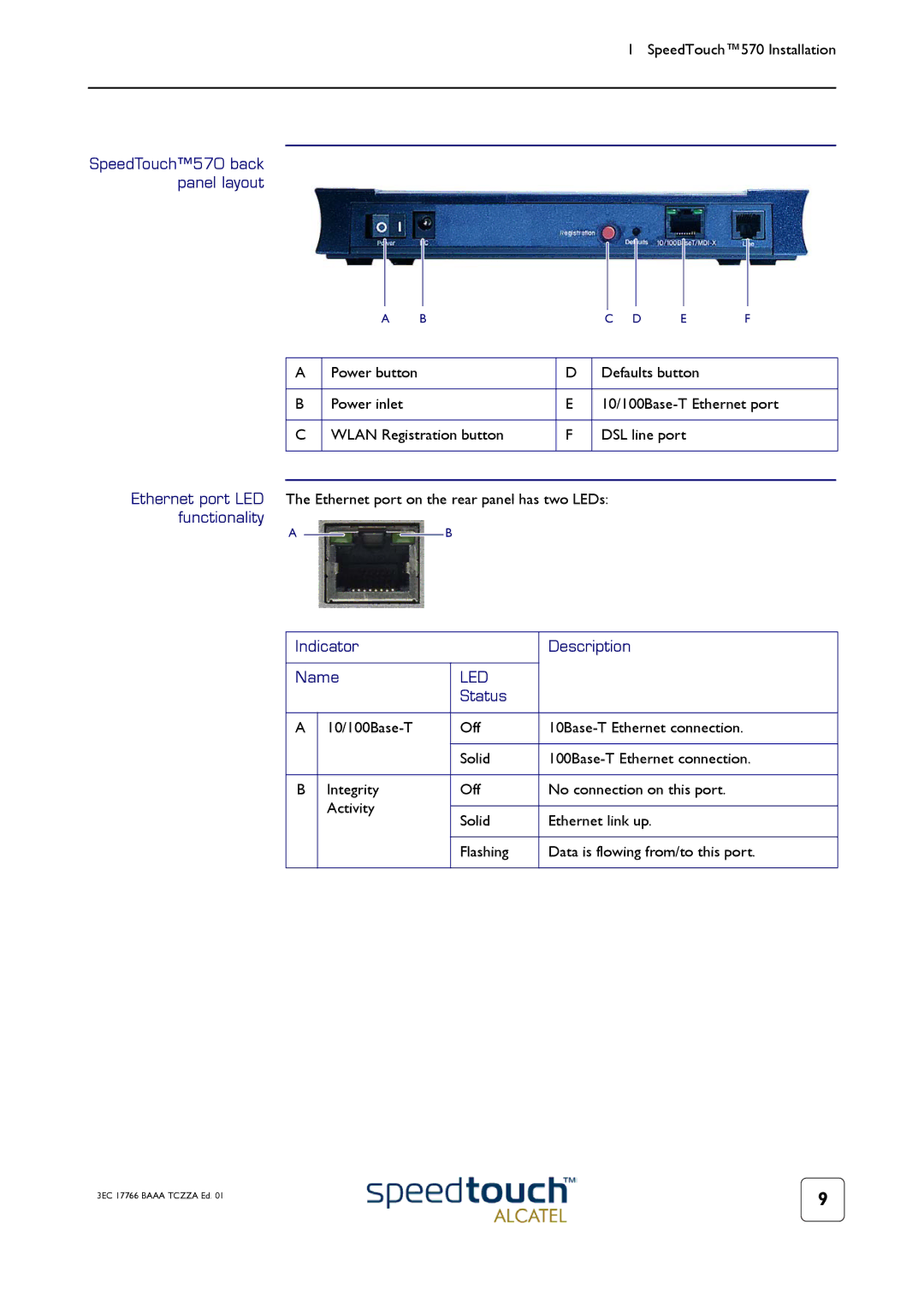
SpeedTouch™570 back panel layout
A BC D E F
A | Power button | D | Defaults button |
|
|
|
|
B | Power inlet | E | |
|
|
|
|
C | WLAN Registration button | F | DSL line port |
|
|
|
|
Ethernet port LED The Ethernet port on the rear panel has two LEDs: functionality
A ![]()
![]()
![]()
![]() B
B
Indicator |
| Description | |
|
|
| |
Name | LED |
| |
|
| Status |
|
|
|
|
|
A | Off | ||
|
|
|
|
|
| Solid | |
|
|
|
|
B | Integrity | Off | No connection on this port. |
| Activity |
|
|
| Solid | Ethernet link up. | |
|
| ||
|
|
|
|
|
| Flashing | Data is flowing from/to this port. |
|
|
|
|
3EC 17766 BAAA TCZZA Ed. 01 | 9 |
|
