8.5.Ethernet Configuration
Ethernet is commonly used for factory automation busses with a computer or PLC acting as a master. The communications protocol used for the Ethernet configuration is MODBUS TCP/IP. For details on the MODBUS TCP/IP specification, please see http://www.modbus.org/.
A Windows software application, DeviceInstaller, is available for configuring the Ethernet module used in the M465M. This application is available for download here:
8.5.1.Hardware Setup for Configuring the Ethernet
Module
To make the
A simple network can easily be constructed for this purpose by using a small broadband router commonly used for home networks. The M465M and a PC can then be connected to the router and the router’s DHCP server will assign IP Addresses to both the PC and the M465M, enabling them to communicate.
8.5.2.Verifying Network Hardware Connection
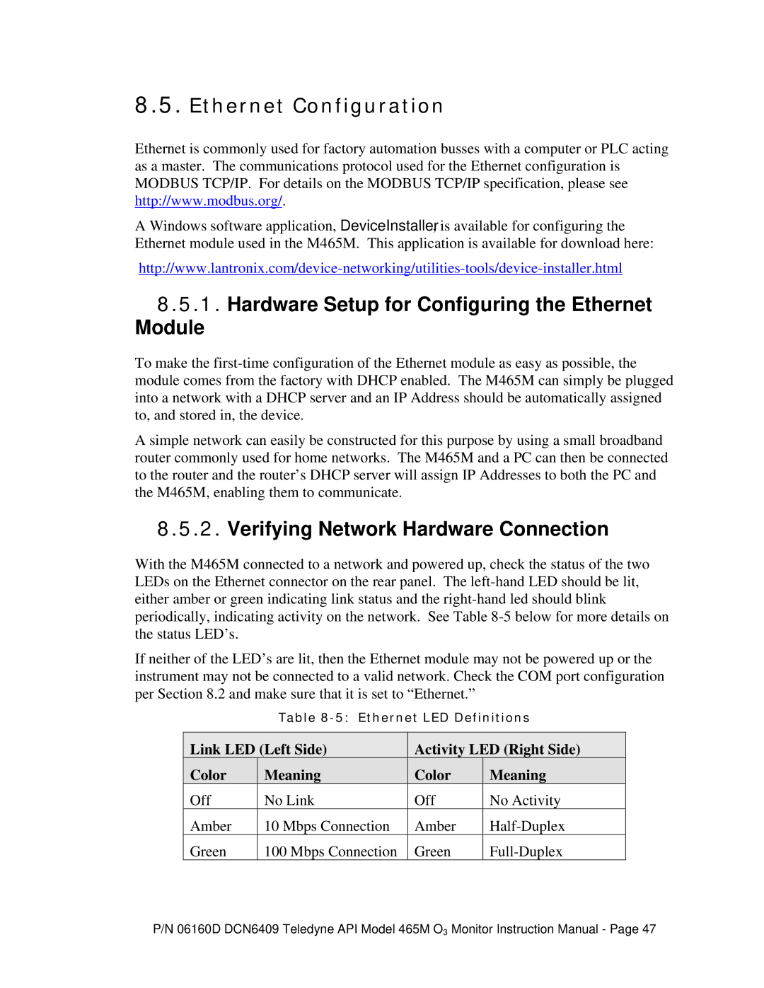
With the M465M connected to a network and powered up, check the status of the two LEDs on the Ethernet connector on the rear panel. The
If neither of the LED’s are lit, then the Ethernet module may not be powered up or the instrument may not be connected to a valid network. Check the COM port configuration per Section 8.2 and make sure that it is set to “Ethernet.”
Table
Link LED (Left Side) | Activity LED (Right Side) | ||||
Color | Meaning | Color |
| Meaning |
|
Off | No Link | Off |
| No Activity | |
Amber | 10 Mbps Connection | Amber | |||
Green | 100 Mbps Connection | Green |
| ||
P/N 06160D DCN6409 Teledyne API Model 465M O3 Monitor Instruction Manual - Page 47