Installation 15
♦♦ Bridging impedance (10k ohms)
Analog Input XLR
PIN DESCRIPTION
1Ground
2Audio +
3Audio -
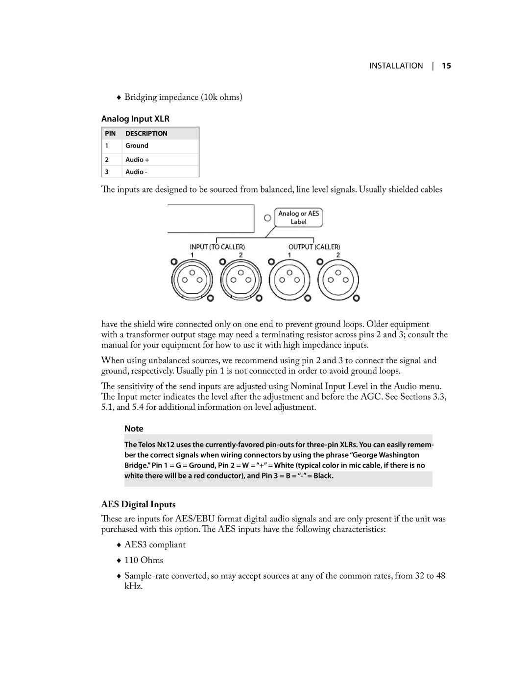
The inputs are designed to be sourced from balanced, line level signals. Usually shielded cables
have the shield wire connected only on one end to prevent ground loops. Older equipment with a transformer output stage may need a terminating resistor across pins 2 and 3; consult the manual for your equipment for how to use it with high impedance inputs.
When using unbalanced sources, we recommend using pin 2 and 3 to connect the signal and ground, respectively. Usually pin 1 is not connected in order to avoid ground loops.
The sensitivity of the send inputs are adjusted using Nominal Input Level in the Audio menu. The Input meter indicates the level after the adjustment and before the AGC. See Sections 3.3, 5.1, and 5.4 for additional information on level adjustment.
Note
The Telos Nx12 uses the
AES Digital Inputs
These are inputs for AES/EBU format digital audio signals and are only present if the unit was purchased with this option. The AES inputs have the following characteristics:
♦♦ AES3 compliant ♦♦ 110 Ohms
♦♦