www.ti.com | Registers |
3.13 HC Head Done Register (HCDONEHEAD)
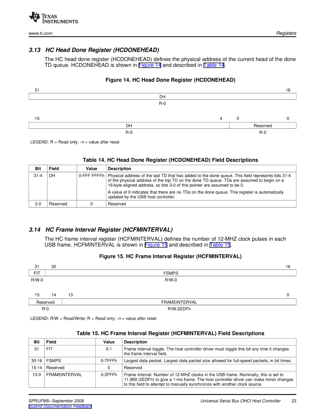
The HC head done register (HCDONEHEAD) defines the physical address of the current head of the done TD queue. HCDONEHEAD is shown in Figure 14 and described in Table 14.
Figure 14. HC Head Done Register (HCDONEHEAD)
31 |
|
| 16 |
| DH |
|
|
|
|
| |
15 | 4 | 3 | 0 |
DH |
|
| Reserved |
|
|
LEGEND: R = Read only;
Table 14. HC Head Done Register (HCDONEHEAD) Field Descriptions
Bit | Field | Value | Description |
DH |
| Physical address of the last TD that has added to the done queue. This field represents bits | |
|
|
| of the physical address of the top TD on the done TD queue. TDs are assumed to begin on a |
|
|
| |
|
|
| A value of 0 indicates that there are no TDs on the done queue. This register is automatically |
|
|
| updated by the USB host controller. |
Reserved | 0 | Reserved |
3.14 HC Frame Interval Register (HCFMINTERVAL)
The HC frame interval register (HCFMINTERVAL) defines the number of
|
|
| Figure 15. HC Frame Interval Register (HCFMINTERVAL) |
| |
31 | 30 |
|
| 16 |
|
FIT |
|
|
| FSMPS |
|
|
|
|
| ||
15 | 14 | 13 |
| 0 |
|
Reserved |
|
| FRAMEINTERVAL |
| |
|
|
| |||
LEGEND: R/W = Read/Write; R = Read only; |
| ||||
|
| Table 15. HC Frame Interval Register (HCFMINTERVAL) Field Descriptions |
| ||
Bit | Field |
| Value | Description |
|
31 | FIT |
| Frame interval toggle. The host controller driver must toggle this bit any time it changes |
| |
|
|
|
| the frame interval field. |
|
FSMPS |
| Largest data packet. Largest data packet size allowed for | |||
Reserved |
| 0 | Reserved |
| |
FRAMEINTERVAL | Frame interval. Number of |
| |||
|
|
|
| 11,999 (2EDFh) to give a | |
|
|
|
| to this field to attempt to manually synchronize with another clock source. |
|
|
| Universal Serial Bus OHCI Host Controller | 23 | ||
Submit Documentation Feedback |
|
|
| ||