www.ti.com | Registers |
3.19 HC Root Hub A Register (HCRHDESCRIPTORA)
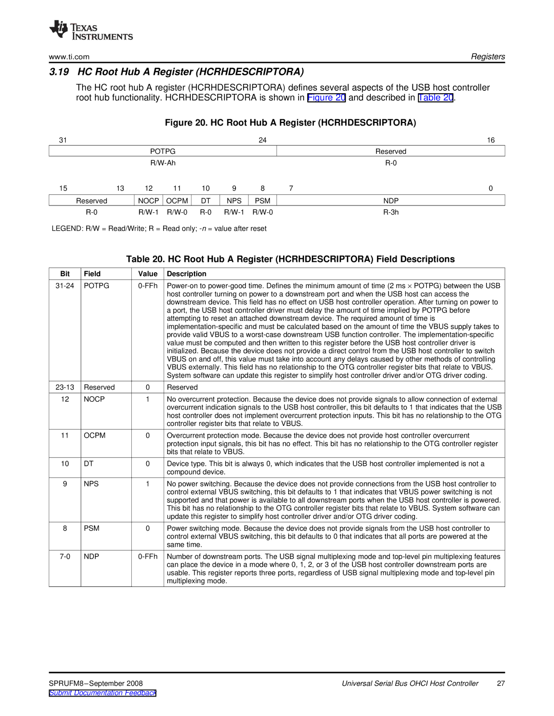
The HC root hub A register (HCRHDESCRIPTORA) defines several aspects of the USB host controller root hub functionality. HCRHDESCRIPTORA is shown in Figure 20 and described in Table 20.
Figure 20. HC Root Hub A Register (HCRHDESCRIPTORA)
31 |
|
|
|
|
| 24 |
| 16 |
|
| POTPG |
|
|
|
| Reserved | |
|
|
|
|
|
| |||
15 | 13 | 12 | 11 | 10 | 9 | 8 | 7 | 0 |
Reserved |
| NOCP | OCPM | DT | NPS | PSM |
| NDP |
|
| |||||||
LEGEND: R/W = Read/Write; R = Read only;
Table 20. HC Root Hub A Register (HCRHDESCRIPTORA) Field Descriptions
Bit | Field | Value | Description |
POTPG | |||
|
|
| host controller turning on power to a downstream port and when the USB host can access the |
|
|
| downstream device. This field has no effect on USB host controller operation. After turning on power to |
|
|
| a port, the USB host controller driver must delay the amount of time implied by POTPG before |
|
|
| attempting to reset an attached downstream device. The required amount of time is |
|
|
| |
|
|
| provide valid VBUS to a |
|
|
| value must be computed and then written to this register before the USB host controller driver is |
|
|
| initialized. Because the device does not provide a direct control from the USB host controller to switch |
|
|
| VBUS on and off, this value must take into account any delays caused by other methods of controlling |
|
|
| VBUS externally. This field has no relationship to the OTG controller register bits that relate to VBUS. |
|
|
| System software can update this register to simplify host controller driver and/or OTG driver coding. |
Reserved | 0 | Reserved | |
12 | NOCP | 1 | No overcurrent protection. Because the device does not provide signals to allow connection of external |
|
|
| overcurrent indication signals to the USB host controller, this bit defaults to 1 that indicates that the USB |
|
|
| host controller does not implement overcurrent protection inputs. This bit has no relationship to the OTG |
|
|
| controller register bits that relate to VBUS. |
11 | OCPM | 0 | Overcurrent protection mode. Because the device does not provide host controller overcurrent |
|
|
| protection input signals, this bit has no effect. This bit has no relationship to the OTG controller register |
|
|
| bits that relate to VBUS. |
10 | DT | 0 | Device type. This bit is always 0, which indicates that the USB host controller implemented is not a |
|
|
| compound device. |
9 | NPS | 1 | No power switching. Because the device does not provide connections from the USB host controller to |
|
|
| control external VBUS switching, this bit defaults to 1 that indicates that VBUS power switching is not |
|
|
| supported and that power is available to all downstream ports when the USB host controller is powered. |
|
|
| This bit has no relationship to the OTG controller register bits that relate to VBUS. System software can |
|
|
| update this register to simplify host controller driver and/or OTG driver coding. |
8 | PSM | 0 | Power switching mode. Because the device does not provide signals from the USB host controller to |
|
|
| control external VBUS switching, this bit defaults to 0 that indicates that all ports are powered at the |
|
|
| same time. |
NDP | Number of downstream ports. The USB signal multiplexing mode and | ||
|
|
| can place the device in a mode where 0, 1, 2, or 3 of the USB host controller downstream ports are |
|
|
| usable. This register reports three ports, regardless of USB signal multiplexing mode and |
|
|
| multiplexing mode. |
| Universal Serial Bus OHCI Host Controller | 27 |
Submit Documentation Feedback |
|
|