4 Replacement Procedures

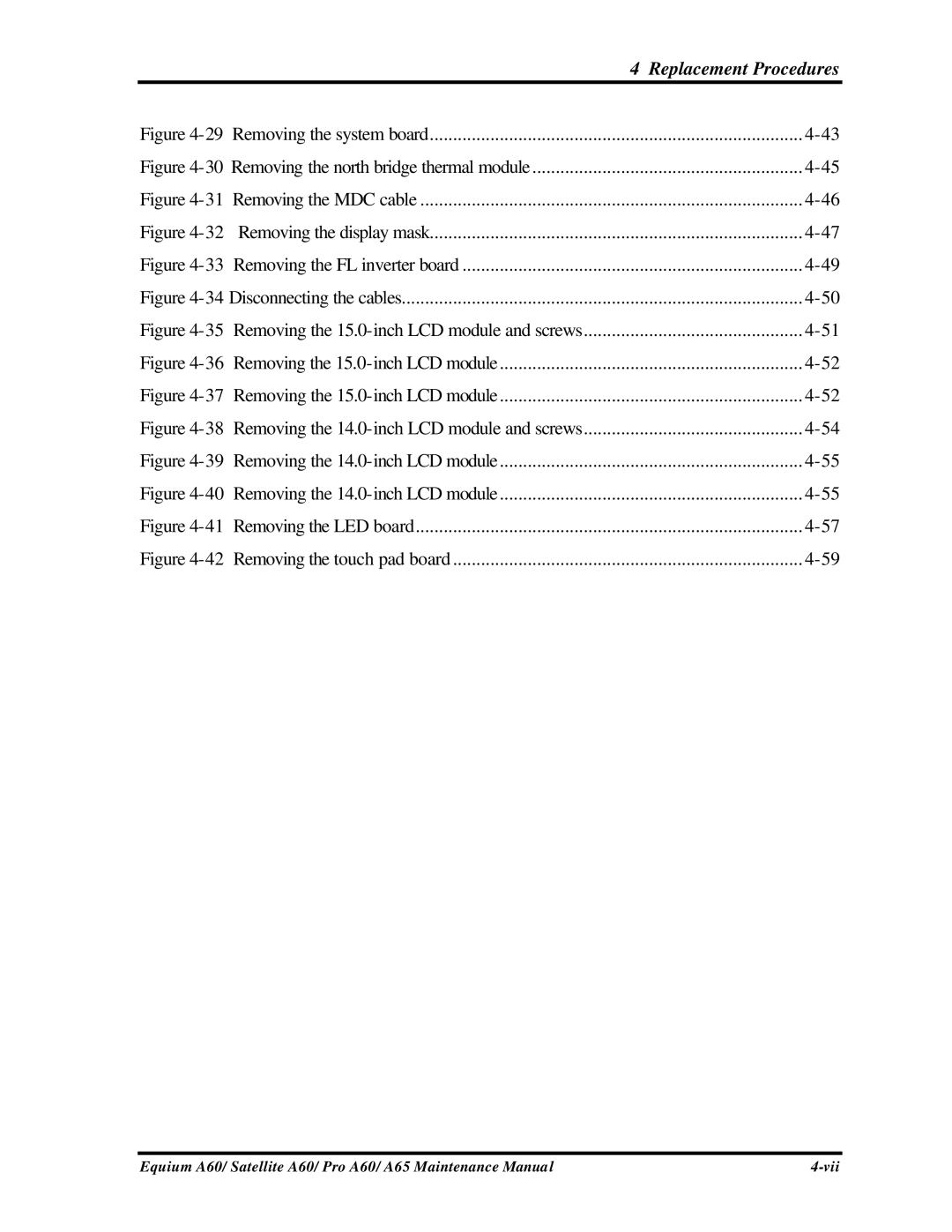
Figure 4-29 Removing the system board

4-43

Figure 4-30 Removing the north bridge thermal module

4-45

Figure 4-31 Removing the MDC cable

4-46

Figure 4-32 Removing the display mask

4-47

Figure 4-33 Removing the FL inverter board

4-49

Figure 4-34 Disconnecting the cables

4-50

Figure 4-35 Removing the 15.0-inch LCD module and screws

4-51

Figure 4-36 Removing the 15.0-inch LCD module

4-52

Figure 4-37 Removing the 15.0-inch LCD module

4-52

Figure 4-38 Removing the 14.0-inch LCD module and screws

4-54

Figure 4-39

Removing the 14.0-inch LCD module

4-55

Figure 4-40

Removing the 14.0-inch LCD module

4-55

Figure 4-41

Removing the LED board

4-57

Figure 4-42

Removing the touch pad board

4-59

Equium A60/ Satellite A60/ Pro A60/ A65 Maintenance Manual

4-vii

Page 144
Image 144
Toshiba A65, PRO A60, SATELLITE A60 manual Removing the system board