4.1 General | 4 Replacement Procedures |
4.1General
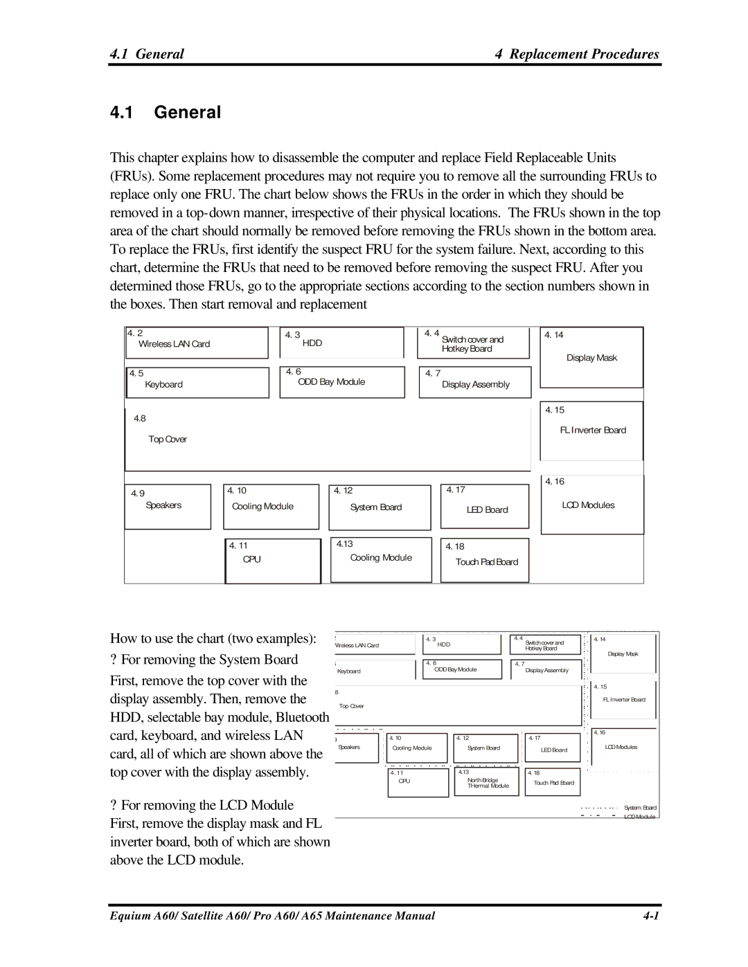
This chapter explains how to disassemble the computer and replace Field Replaceable Units (FRUs). Some replacement procedures may not require you to remove all the surrounding FRUs to replace only one FRU. The chart below shows the FRUs in the order in which they should be removed in a
4.2
Wireless LAN Card
4.5
Keyboard
4.8
Top Cover
4. 9
Speakers
4. 3 | 4. 4 | |
HDD | Switch cover and | |
HotkeyBoard | ||
| ||
4. 6 | 4. 7 | |
ODD Bay Module | Display Assembly | |
|
4. 10 |
| 4. 12 |
| 4. 17 | |
Cooling Module |
|
| System Board |
| LED Board |
|
|
|
|
| |
|
|
|
|
|
|
|
|
|
|
|
|
4. 11 |
|
| 4.13 |
| 4. 18 |
CPU |
| Cooling Module |
| Touch Pad Board | |
|
|
|
|
| |
|
|
|
|
|
|
4. 14
Display Mask
4. 15
FL Inverter Board
4. 16
LCD Modules
How to use the chart (two examples): 4. 2 | ||
| Wireless LAN Card | |
? For removing the System Board | 4.5 | |
First, remove the top cover with the |
| Keyboard |
|
| |
display assembly. Then, remove the | 4.8 | |
| Top Cover | |
|
| |
HDD, selectable bay module, Bluetooth | ||
card, keyboard, and wireless LAN |
|
|
4.9 | ||
card, all of which are shown above the |
| Speakers |
|
| |
top cover with the display assembly. |
|
|
?For removing the LCD Module First, remove the display mask and FL inverter board, both of which are shown above the LCD module.
4. 3 |
| 4.4 |
| HDD | Switchcoverand |
| Hotkey Board | |
|
|
4. 6 |
|
| 4. 7 |
| |
ODD Bay Module |
|
| Display Assembly | ||
4. 10 |
|
|
|
| |
| 4. 12 |
|
| 4. 17 | |
Cooling Module |
| System Board |
|
| LED Board |
|
|
|
|
| |
|
|
|
|
|
|
|
|
|
|
|
|
4. 11 |
| 4.13 |
|
| 4. 18 |
CPU | North Bridge |
|
| Touch Pad Board | |
|
| THermal Module |
|
| |
|
|
|
|
| |
|
|
|
|
|
|
4. 14
Display Mask
4. 15
FL Inverter Board
4.16
LCD Modules
System Board
LCD Module
Equium A60/ Satellite A60/ Pro A60/ A65 Maintenance Manual |