E658130
5.5.7. Remote Register Assignment
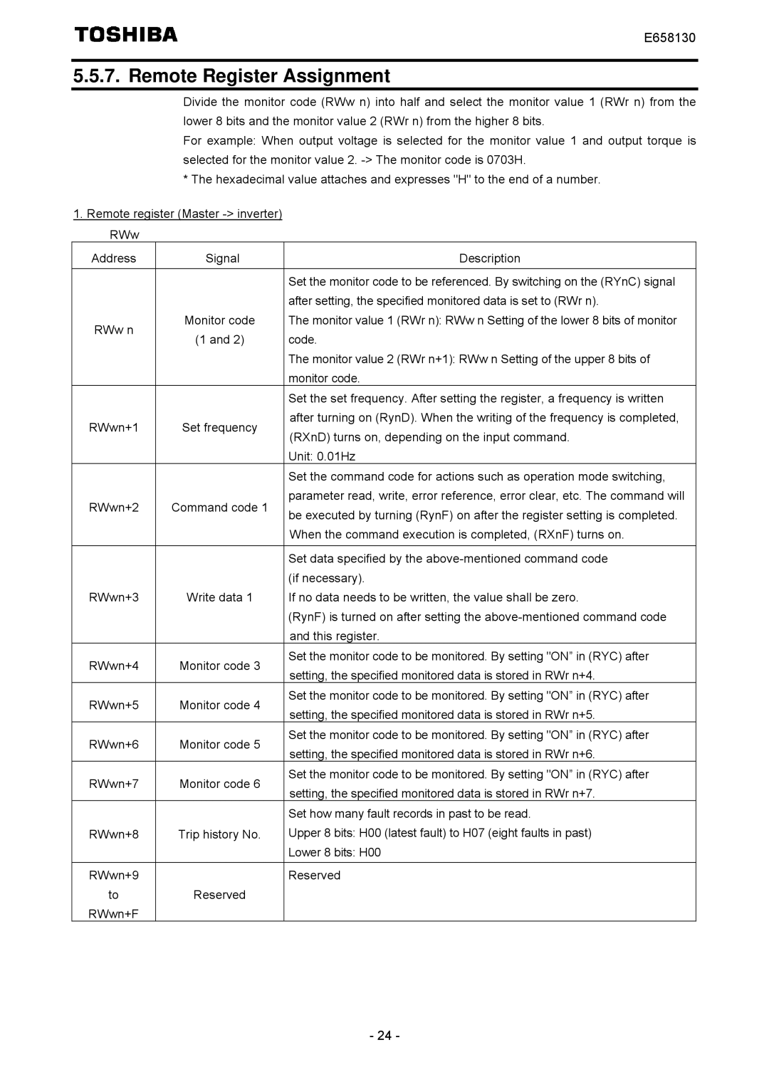
Divide the monitor code (RWw n) into half and select the monitor value 1 (RWr n) from the lower 8 bits and the monitor value 2 (RWr n) from the higher 8 bits.
For example: When output voltage is selected for the monitor value 1 and output torque is selected for the monitor value 2.
*The hexadecimal value attaches and expresses "H" to the end of a number.
1.Remote register (Master
RWw
Address | Signal | Description | |
|
|
| |
|
| Set the monitor code to be referenced. By switching on the (RYnC) signal | |
|
| after setting, the specified monitored data is set to (RWr n). | |
RWw n | Monitor code | The monitor value 1 (RWr n): RWw n Setting of the lower 8 bits of monitor | |
(1 and 2) | code. | ||
| |||
|
| The monitor value 2 (RWr n+1): RWw n Setting of the upper 8 bits of | |
|
| monitor code. | |
|
| Set the set frequency. After setting the register, a frequency is written | |
RWwn+1 | Set frequency | after turning on (RynD). When the writing of the frequency is completed, | |
(RXnD) turns on, depending on the input command. | |||
|
| ||
|
| Unit: 0.01Hz | |
|
| Set the command code for actions such as operation mode switching, | |
RWwn+2 | Command code 1 | parameter read, write, error reference, error clear, etc. The command will | |
be executed by turning (RynF) on after the register setting is completed. | |||
|
| ||
|
| When the command execution is completed, (RXnF) turns on. | |
|
|
| |
|
| Set data specified by the | |
|
| (if necessary). | |
RWwn+3 | Write data 1 | If no data needs to be written, the value shall be zero. | |
|
| (RynF) is turned on after setting the | |
|
| and this register. | |
RWwn+4 | Monitor code 3 | Set the monitor code to be monitored. By setting "ON” in (RYC) after | |
setting, the specified monitored data is stored in RWr n+4. | |||
|
| ||
RWwn+5 | Monitor code 4 | Set the monitor code to be monitored. By setting "ON” in (RYC) after | |
setting, the specified monitored data is stored in RWr n+5. | |||
|
| ||
RWwn+6 | Monitor code 5 | Set the monitor code to be monitored. By setting "ON” in (RYC) after | |
setting, the specified monitored data is stored in RWr n+6. | |||
|
| ||
RWwn+7 | Monitor code 6 | Set the monitor code to be monitored. By setting "ON” in (RYC) after | |
setting, the specified monitored data is stored in RWr n+7. | |||
|
| ||
|
| Set how many fault records in past to be read. | |
RWwn+8 | Trip history No. | Upper 8 bits: H00 (latest fault) to H07 (eight faults in past) | |
|
| Lower 8 bits: H00 | |
|
|
| |
RWwn+9 |
| Reserved | |
to | Reserved |
| |
RWwn+F |
|
|
- 24 -
