E658130
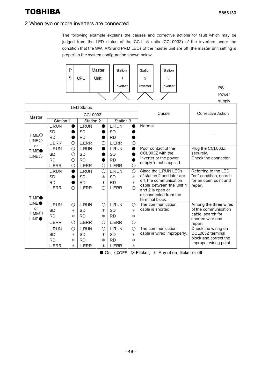
2.When two or more inverters are connected
The following example explains the causes and corrective actions for fault which may be judged from the LED status of the
|
|
| P |
|
| Master |
| Station |
|
| Station |
|
|
| Station |
|
| ||||
|
|
| S | CPU |
| Unit |
| 1 |
|
| 2 |
|
| 3 |
|
| |||||
|
|
|
|
|
|
|
|
|
|
|
| Inverter |
|
| Inverter |
|
|
| Inverter |
| PS: |
|
|
|
|
|
|
|
|
|
|
|
|
|
|
|
|
|
|
|
|
| |
|
|
|
|
|
|
|
|
|
|
|
|
|
|
|
|
|
|
|
|
| Power |
|
|
|
|
|
|
|
|
|
|
|
|
|
|
|
|
|
|
|
|
| |
|
|
|
|
|
|
|
|
|
|
|
|
|
|
|
|
|
|
|
|
| supply |
|
|
|
|
|
|
|
|
|
|
|
|
|
|
|
|
|
|
|
|
| |
|
|
|
| LED Status |
|
|
|
|
|
|
|
|
|
|
|
|
|
| |||
|
|
|
|
|
|
|
|
|
|
|
|
|
|
|
| Cause | Corrective Action | ||||
Master |
|
|
|
|
| CCL003Z |
|
|
|
| |||||||||||
|
|
|
|
|
|
|
|
|
|
|
|
|
|
|
|
|
|
|
|
| |
| Station 1 |
|
| Station 2 |
|
| Station 3 |
|
|
|
|
|
|
|
| ||||||
| L.RUN | ● | L.RUN |
| ● |
| L.RUN | ● | Normal |
| |||||||||||
TIME○ | SD | ● | SD |
| ● |
| SD | ● |
|
|
|
|
|
| - | ||||||
RD | ● | RD |
| ● |
| RD | ● |
|
|
|
|
|
| ||||||||
LINE○ |
|
|
|
|
|
|
|
|
| ||||||||||||
L.ERR | ○ | L.ERR |
| ○ |
| L.ERR | ○ |
|
|
|
|
|
|
| |||||||
or |
|
|
|
|
|
|
|
|
| ||||||||||||
L.RUN | ○ | L.RUN |
| ● |
| L.RUN | ● | Poor contact of the | Plug the CCL003Z | ||||||||||||
TIME● |
|
| |||||||||||||||||||
SD | ○ | SD |
| ● |
| SD | ● | CCL003Z with the | securely. | ||||||||||||
LINE○ |
|
| |||||||||||||||||||
RD | ○ | RD |
| ● |
| RD | ● | Inverter or the power | Check the connector. | ||||||||||||
|
|
| |||||||||||||||||||
| L.ERR | ○ | L.ERR |
| ○ |
| L.ERR | ○ | supply is not supplied. |
| |||||||||||
|
|
|
|
|
|
|
|
|
| ||||||||||||
| L.RUN | ● | L.RUN |
| ○ |
| L.RUN | ○ | Since the L.RUN LEDs | Referring to the LED | |||||||||||
| SD | ● | SD |
| * |
| SD | * | of station 2 and later are | "on" condition, search | |||||||||||
| RD | ● | RD |
| * |
| RD | * | off, the communication | for an open point and | |||||||||||
| L.ERR | ○ | L.ERR |
| ○ |
| L.ERR | ○ | cable between the unit 1 | repair. | |||||||||||
|
|
| and 2 is open or |
| |||||||||||||||||
TIME● |
|
|
|
|
|
|
|
|
|
|
|
|
|
| disconnected from the |
| |||||
|
|
|
|
|
|
|
|
|
|
|
|
|
| terminal block. |
| ||||||
LINE● |
|
|
|
|
|
|
|
|
|
|
|
|
|
|
| ||||||
L.RUN | ○ | L.RUN |
| ○ |
| L.RUN | ○ | The communication | Among the three wires | ||||||||||||
or | SD | * | SD |
| * |
| SD | * | cable is shorted. | of the communication | |||||||||||
TIME○ | RD | * | RD |
| * |
| RD | * |
|
|
|
|
|
| cable, search for | ||||||
LINE● |
|
|
|
|
|
|
|
| shorted wire and | ||||||||||||
L.ERR | ○ | L.ERR |
| ○ |
| L.ERR | ○ |
|
|
|
|
|
| ||||||||
|
|
|
|
|
|
|
|
| repair. | ||||||||||||
| L.RUN | ○ | L.RUN |
| ○ |
| L.RUN | ○ | The communication | Check the wiring on | |||||||||||
| SD | * | SD |
| * |
| SD | * | cable is wired improperly. | CCL003Z terminal | |||||||||||
| RD | * | RD |
| * |
| RD | * |
|
|
|
|
|
| block and correct the | ||||||
|
|
|
|
|
|
|
|
| improper wiring point. | ||||||||||||
| L.ERR | * | L.ERR |
| * |
| L.ERR | * |
|
|
|
|
|
| |||||||
|
|
|
|
|
|
|
|
|
| ||||||||||||
|
|
|
|
|
|
|
|
| ●:On, | ○:OFF, ◎:Flicker, | *: Any of on, flicker or off. | ||||||||||
- 49 -