Super Modular Multi
Page
Super Modular Multi System Contents
Outline of Toshiba Super Modular Multi System S-MMS
Outdoor unit Indoor unit
Self-diagnostic system
Compact
Largest system capacity
Energy saving design
Summary of system equipment
Technical specifications outdoor units
Technical specifications combination of outdoor units
Branching joints and headers
Outdoor unit model line-up cooling only units
Product designation
Combined capacity range
Rated conditions
Outdoor unit model line-up heat pump units
MMY- M AP 000 0 H T
Technical specifications indoor units
Remote controller
Simplified remote controller Connected to indoor unit
Wireless remote controller kit Connected to indoor unit
TCB-AX21U W-E
Master
Weekly timer RBC-EXW21E Connected to central remote
Controller, wired remote controller
8HP
Basic system configuration
System legend example 8 hp system
Hp system
10HP
10HP 10HP
Hp system
10HP 10HP 10HP
Outdoor unit Indoor unit Remote controller
Equipment selection procedure
Selection flow chart
Indoor unit and outdoor unit combination
Capacity code
Capacity correction value Indoor air wet bulb temperature C
Correction of outdoor unit diversity
Capacity correction value Indoor air dry bulb temperature C
Correction of outdoor unit diversity
Operating temperature range
Heating mode
Capacity calculation for each indoor unit
Rated conditions
Outside view
Example of equipment selection
Selection criteria for each floor
Procedure and result of equipment selection
Air conditioning load Equipment selection Floor Room No
Indoor unit Outdoor unit Model Capacity kW Cooling Heating
Cooling Heating
Example Equipment selection based on system load profile
Load in each room
Schematic diagram
MMY-AP2801T8 MMY-AP2801HT8
Refrigerant piping design
Check of concentration limit
Free branching system
Line branching system Header branching system
Allowable value Piping section
Allowable length/height difference of refrigerant piping
System restrictions
Gas side Liquid side
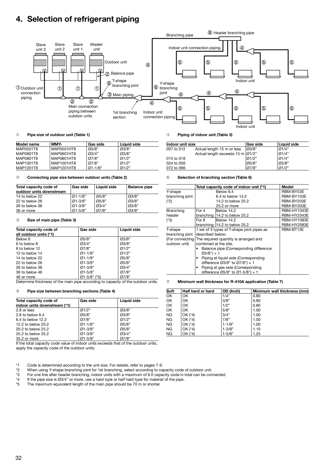
Selection of refrigerant piping
Pipe size of outdoor unit Table Model name
Charging requirement with additional refrigerant
Calculating the amount of additional refrigerant required
Charge Cooling only
Liquid side pipe diameter
Wiring design
Outdoor unit power supply
Electrical wiring design
General
Control wiring design
Control wiring diagram
Control wiring between outdoor units L5 Wiring
Type
Length
Design
FLA MCA Mocp
Compressor Fan motor Power supply
Single outdoor unit Heat pump Cooling only Nominal
Voltage Range Ph-Hz Min Max
Combination of outdoor units Heat pump Cooling only Nominal
Control via indoor remote controller
Control via the central remote controller
Controls
Range of controls to meet various system needs
Applications for indoor remote controller
Basic function System diagram Model Individual control
Two remote controllers
Control by weekly timer
Application controls for central remote controller
Basic function System diagram Model
Indoor remote controller
Function of central remote controller
Available
TCB-PCNT30TLE
Application control for network
TCB-1FLN
BACnet
BMS-LSV
BMS-TP5120ACE
Accessories
Indoor unit accessories
Remote controller
Indoor unit type Accessory name Model Applicable model
Technical specifications
Indoor units Way ceiling cassettes
RBC-UW136PG RBC-UW266PG
Room thermostat
RBC-UY135PG RBC-US165PG RBC-US265PG
Fan motor power input
Static pressure factory setting Static pressure max
Indoor units Standard ducted units
Sound pressure level high/medium/low** dBA
Unit weight
Static pressure factory setting
Sound power level high
Indoor units High-pressure ducted units
Indoor units Slim duct units
Lower air inlet Sound power level high/medium/low
Rear air inlet Sound power level high/medium/low
Indoor units Ceiling-suspended units
Indoor units High-wall units 1 Series
Indoor units High-wall units 2 Series
Indoor units Floor-mounted console units
Indoor units Concealed chassis units
Static pressure
Indoor units Floor-mounted cabinet units
Outdoor units
Outdoor units combination
DBA 74.5
DBA 75.0
24.26 Power factor, cooling Operating current, cooling 30.51
258 256
DBA 76.5
77.0
Max. number of connectable indoor units High-pressure switch
Power supply ± 10% Ph-Hz 400-3-50
130.0 135.0
Fan characteristics
Case of square duct flange of discharge section
MMD-AP0071BH, AP0091BH
MMD-AP0121BH
MMD-AP0241BH, AP0271BH
MMD-AP0361BH
MMD-AP0301BH
MMD-AP0481BH, AP0561BH
High-pressure ducted unit
MMD-AP0181H
MMD-AP0241H, AP0271H
MMD-AP0361H
MMD-AP0721H
MMD-AP0961H
MMD-AP0151SPH MMD-AP0181SPH
Slim duct unit
MMD-AP0071SPH, AP0091SPH MMD-AP0121SPH
Slim duct unit with filter attached
MMD-AP0151SPH
Dimensional drawings
All dimensions are given in mm
Indoor unit 4-way ceiling cassette
MMU-AP0091H to P0561H
MMU-AP0071WH, AP0091WH, AP0121WH
All dimensions are given in mm View
Indoor unit 2-way ceiling cassette
Model MMU-AP0151WH to AP0181WH MMU-AP0241WH to AP0301WH
View Space required for installation and servicing
MMU-AP0151WH, AP0181WH, AP0241WH, AP0271WH, AP0301WH
MMU-AP0481WH
Indoor unit 1-way ceiling cassette
MMU-AP0071YH, AP0091YH, AP0121YH
AP0241SH
MMU-AP0151SH, AP0181SH, AP0241SH
View Model MMU AP0151SH, AP0181SH
Indoor unit standard ducted unit
MMD-AP0271H, AP0961H
View Space required for installation and servicing *1
Indoor unit high-pressure ducted unit
Indoor unit slim duct unit
MMD-AP0071SPH, AP0091SPH, AP0121SPH, AP0151SPH, AP0181SPH
Bottom view complete with filter
Bottom view excluding filter
Indoor unit ceiling-suspended unit
MMC-AP0151H, AP0181H, AP0241H, AP0271H, AP0361H, AP0481H
Model MMC AP0151H, AP0181H
AP0241H to AP0271H
Indoor unit high-wall unit 1 Series
MMK-AP0071H, AP0091H, AP0121H
MMK-AP0151H, AP0181H
MMK-AP0241H
Indoor unit high-wall unit 2 Series
MMK-AP0072H, AP0092H, AP0122H
Indoor unit floor-mounted console unit
MML-AP0071H, AP0091H, AP0121H, AP0151H, AP0181H, AP0241H
Indoor unit concealed chassis unit
No. Name
Model MML AP0071BH, AP0091BH, AP0121BH
AP0151BH, AP0181H
MMF-AP0151H, AP0181H, AP0241H, AP0271H
Space required for service For right-hand piping
Indoor unit floor-mounted cabinet unit
MMF-AP0361H, AP0481H, AP0561H
Refrigerant pipe positions Details of hole for rear piping
Remote controller
All dimensions are given in mm
Wireless remote controller kit
Weekly timer
TCB-AX21E
RBC-EXW21E
Central remote controller
TCB-SC642TLE
LON Gateway
TCB-IFLN
Touch-screen controller BMS-TP5120ACE
TCS-Net relay interface
BMS-IFLSV1E
Energy monitoring relay interface BMS-IFWH3E
Intelligent server
BMS-LSV2E
Windows-based central controller BMS-LSV
Digital I/O relay interface
BMS-IFDD01E
Outdoor module
Outdoor module Two units connected
Outdoor unit combination Master unit Slave unit
Outdoor module Three units connected
Unit combination
Outdoor module Four units connected
Unit combination Outdoor unit combination Master unit
Model Accessory socket x quantity
Branch header/branch joint
Branch header RBM-HY1043E, HY1083E, HY2043E,HY2083E
Shape branching joint
RBM-BY53E, BY103E
RBM-BY203E, BY303E
Accessory socket
Page
Toshiba Air Conditioning