Models FC & FF “ZO” and later design sequence
Installation, Operation, and Maintenance
UniTrane Fan-Coil & Force Flo Air Conditioners
200 to 1,200 cfm
general information
Warnings and Cautions
About This Manual Literature Change History
Common HVAC Acronyms
contents
Installation ……………………………………………………………2
Maintenance…………………………………………………………60
Operation ……………………………………………………………49
general information
General
Model Number
Installation information
general
Model Number Description
Digit 9 - piping system/placement
Installation information
general
Digit 28 - auxiliary control valve 0 = none
Digit 29 - piping packages 0 = none
Installation information
general
Table I-GI-1. Fan-coil component data
Table I-GI-2. Low vertical fan-coil component data
Available Models
Installation information
general
model A vertical concealed model D horizontal cabinet
Installation information
Factory-Installed Piping Packages
general
dimensions
Installation
weights
Vertical Concealed, Model A
Vertical Cabinet, Model B
dimensions
Installation
weights
Horizontal Concealed, Model C
dimensions
Installation
weights
Horizontal Cabinet, Model D
dimensions
Installation
weights
Horizontal Recessed, Model E
Installation
dimensions
weights
Vertical Wall Hung Cabinet, Model F
Installation
dimensions
weights
Vertical Recessed, Model H
Installation
dimensions
weights
Vertical Slope Top, Model J
Installation
dimensions
weights
Low Vertical Concealed, Model K
Installation
dimensions
weights
Low Vertical Cabinet, Model L
Installation
dimensions
weights
Inverted Vertical Cabinet, Model M
Installation
dimensions
weights
Inverted Vertical Recessed, Model N
Installation
dimensions
weights
Fan-Coil Coil Connections Vertical Units Fan-Coil Coil Connections
Horizontal Units
Installation
dimensions
Force Flo Coil Connections Vertical Units
Force Flo
Coil Connections
Inverted Units
Fresh Air Opening Locations Horizontal Units Models C, D, and E
Installation
dimensions
weights
Fresh Air Opening Locations Vertical Units Models A, B, F, & J
Installation
dimensions
weights
Wall Box
Installation
dimensions
weights
Projection Panel
Installation
dimensions
weights
pre-installation Installation considerations
Installation Preparation
Receiving and Handling
Jobsite Storage
Pre-Installation Checklist
Service Access
pre-installation Installation considerations
Installation requirements
mechanical
Duct Connections
Piping Considerations
Installation requirements
Water Piping Connections to Factory- Installed Piping Package
mechanical
Condensate Drain
mechanical
Installation requirements
Venting the Hydronic Coil
mechanical
Installation requirements
Balancing The Manual Circuit Setter Valve
Installation requirements
mechanical
Steam Piping
Installation requirements
mechanical
Coil Damage
Unit Wiring Diagrams
Supply Power Wiring
Wall Mounted Control Interconnection Wiring
electrical
Installation requirements
electrical
Table I-ER-2. Low vertical free discharge motors, 115 volt
Table I-ER-3. Decimal to fractional HP kW conversion
electrical
Installation requirements
Heater amps = heater kW x 1000/heater voltage
Installation requirements
electrical
Table I-ER-10. Force Flo single-stage, max kW electric heat
Table I-ER-11. Force Flo single stage, low kW electric heat
electrical
Installation requirements
Table I-ER-12. Force Flo 2-stage electric heat
installation
Installation procedure
Installing the Unit
Electrical Wiring
installation
Installation procedure
Note The trim ring assembly cannot accomodate unlevel ceilings
Unit Leveling
Wall-Mounted Control Options
installation
Installation procedure
Figure I-IP-4. Zone sensor with setpoint knob, on/cancel, & comm jack
Installing Wall Mounted Controls
installation
Installation procedure
Wiring Instructions
Installation Checklist
installation
Installation procedure
Unit Leveling
Communication Wiring
Recommended Communication Wiring Practices
pre-startup
Device Addressing
Pre-Startup Checklist
Installation requirements
pre-startup
WARNING Hazardous
Installation startup
Tracer ZN510 & ZN520 Unit Startup
general Operation information
General Information
Manual Fan Mode Switch
Relay Board
Fan Mode Switch Operation
sequence of
Operation operation
Tracer ZN010 & ZN510 Operation
Binary Inputs
Binary Outputs
Power-Up Sequence
Entering Water Temperature Sampling Function
Fan Mode Switch
sequence of
Operation operation
Analog Inputs
Tracer ZN520 Sequence of Operation
sequence of
Operation operation
Occupied
Cooling Operation
Heating Operation
sequence of
Operation operation
Fan Mode Operation
Fan Off Delay
sequence of
Operation operation
Entering Water Temperature Sampling Function
sequence of
Operation operation
Fan Start on High Speed
sequence of
Operation operation
Data Sharing
Binary Outputs
sequence of
Operation operation
Table O-SO-14. Analog inputs
Table O-SO-15. Analog inputs
External Setpoint Adjustment
Fan Switch
On/Cancel Buttons
sequence of
Diagnostics
Maintenance diagnostics
Table M-D-1. Tracer ZN520 Diagnostics
Maintenance diagnostics
Translating Multiple Diagnostics
Resetting Diagnostics
Diagnostic Reset
Maintenance diagnostics
Table M-D-3. Fan outputs do not energize
Table M-D-4. Valves Stay Closed
Table M-D-5. Valves Stay Open
Maintenance diagnostics
Table M-D-6. Electric Heat Not Operating
Table M-D-7. Fresh Air Damper Stays Open
Table M-D-8. Fresh Air Damper Stays Closed
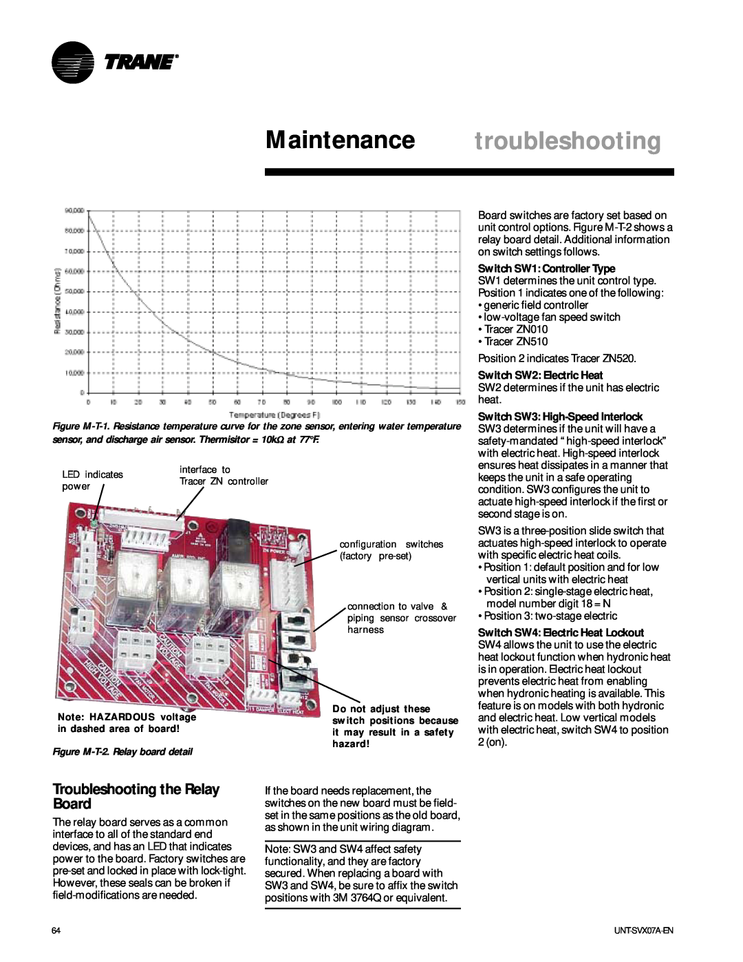
Maintenance troubleshooting
Troubleshooting the Relay Board
Switch SW1 Controller Type
Switch SW2 Electric Heat
Troubleshooting Tracer ZN010, ZN510 & ZN520
Maintenance troubleshooting
Red SERVICE LED
Red SERVICE LED
Maintenance troubleshooting
Verify output wiring and operation without using Rover, service tool
Table M-T-1. Test sequence for 1-heat/1-cool configurations
Force the water valve to open and balance the hydronic system
maintenance
Maintenance procedures
Maintenance Procedures
Main Drain Pan
maintenance
Maintenance procedures
Coil Maintenance
Steam and Hydronic Coil Cleaning Procedure
maintenance
Maintenance procedures
Control Device Replacement
Vertical Units
Periodic Maintenance Checklists
maintenance
Maintenance procedures
Monthly Checklist
Maintenance diagram
typical wiring
CSTI Fan Speed Switch
typical wiring
CSTI Non Fan Speed Switch
Maintenance diagram
typical wiring
Line voltage fan speed switch
Maintenance diagram
typical wiring
Tracer ZN010 with electric heat
Maintenance diagram
typical wiring
Tracer ZN510 with main and auxilliary valves
Maintenance diagram
typical wiring
ZN520 with 2-stage electric heat
Maintenance diagram
Page
Page

 (factory