maintenance
Maintenance procedures
Maintenance Procedures
Perform the following maintenance procedures to ensure proper unit operation.
![]() WARNING
WARNING
Live Electrical Components!
During installation, testing, servicing, and troubleshooting this equipment, it may be necessary to work with live electrical components. Have a qualified licensed electrician or other
All models except vertical cabinets
Remove the front panel of the vertical recessed unit and open the bottom panel door of the horizontal cabinet and horizontal recessed unit to access the filter. The front panel of the vertical cabinet unit does not require removal to change the filter.
Note: Vertical recessed, horizontal cabinet, & horizontal recessed units with a bottom return have filter guides to secure the filter in position. Also, if these
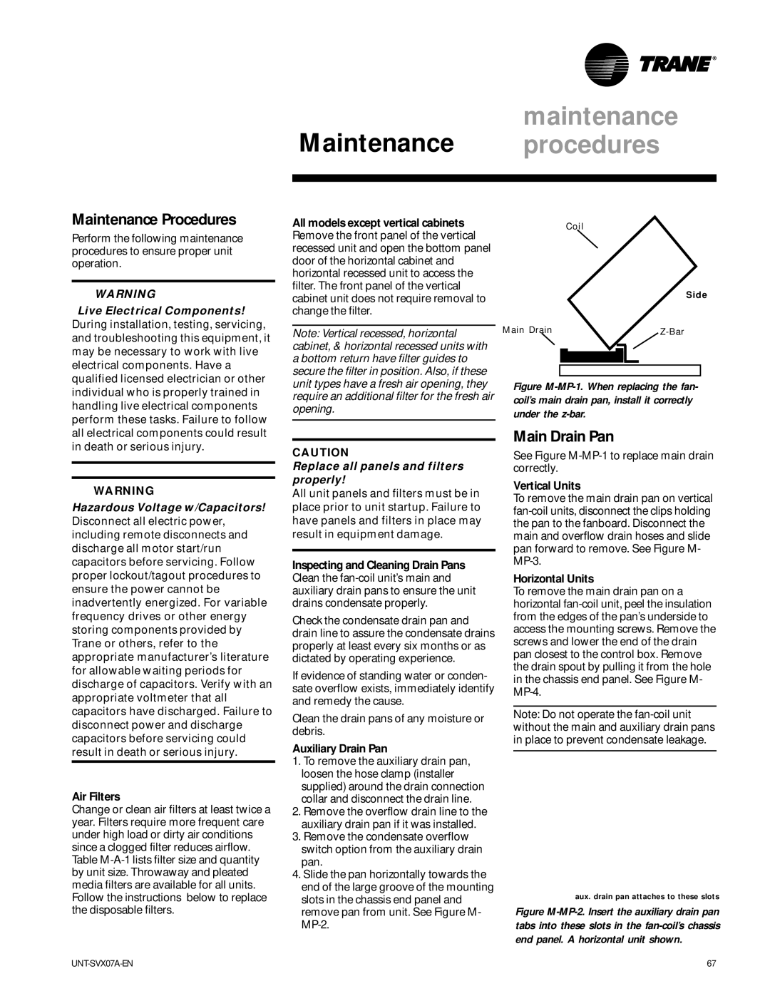
Coil
Main Drain
Side |
individual who is properly trained in handling live electrical components perform these tasks. Failure to follow
unit types have a fresh air opening, they require an additional filter for the fresh air opening.
Figure M-MP-1. When replacing the fan- coil’s main drain pan, install it correctly under the z-bar.
all electrical components could result in death or serious injury.
![]() WARNING
WARNING
Hazardous Voltage w/Capacitors! Disconnect all electric power, including remote disconnects and discharge all motor start/run capacitors before servicing. Follow proper lockout/tagout procedures to ensure the power cannot be inadvertently energized. For variable frequency drives or other energy storing components provided by Trane or others, refer to the appropriate manufacturer’s literature for allowable waiting periods for discharge of capacitors. Verify with an appropriate voltmeter that all capacitors have discharged. Failure to disconnect power and discharge capacitors before servicing could result in death or serious injury.
Air Filters
Change or clean air filters at least twice a year. Filters require more frequent care under high load or dirty air conditions since a clogged filter reduces airflow. Table
CAUTION
Replace all panels and filters properly!
All unit panels and filters must be in place prior to unit startup. Failure to have panels and filters in place may result in equipment damage.
Inspecting and Cleaning Drain Pans Clean the
Check the condensate drain pan and drain line to assure the condensate drains properly at least every six months or as dictated by operating experience.
If evidence of standing water or conden- sate overflow exists, immediately identify and remedy the cause.
Clean the drain pans of any moisture or debris.
Auxiliary Drain Pan
1.To remove the auxiliary drain pan, loosen the hose clamp (installer supplied) around the drain connection collar and disconnect the drain line.
2.Remove the overflow drain line to the auxiliary drain pan if it was installed.
3.Remove the condensate overflow switch option from the auxiliary drain pan.
4.Slide the pan horizontally towards the end of the large groove of the mounting slots in the chassis end panel and remove pan from unit. See Figure M-
Main Drain Pan
See Figure
Vertical Units
To remove the main drain pan on vertical
Horizontal Units
To remove the main drain pan on a horizontal
Note: Do not operate the
aux. drain pan attaches to these slots
Figure M-MP-2. Insert the auxiliary drain pan tabs into these slots in the fan-coil’s chassis end panel. A horizontal unit shown.
67 |