Transition Networks |
|
Connecting DB-9 cable
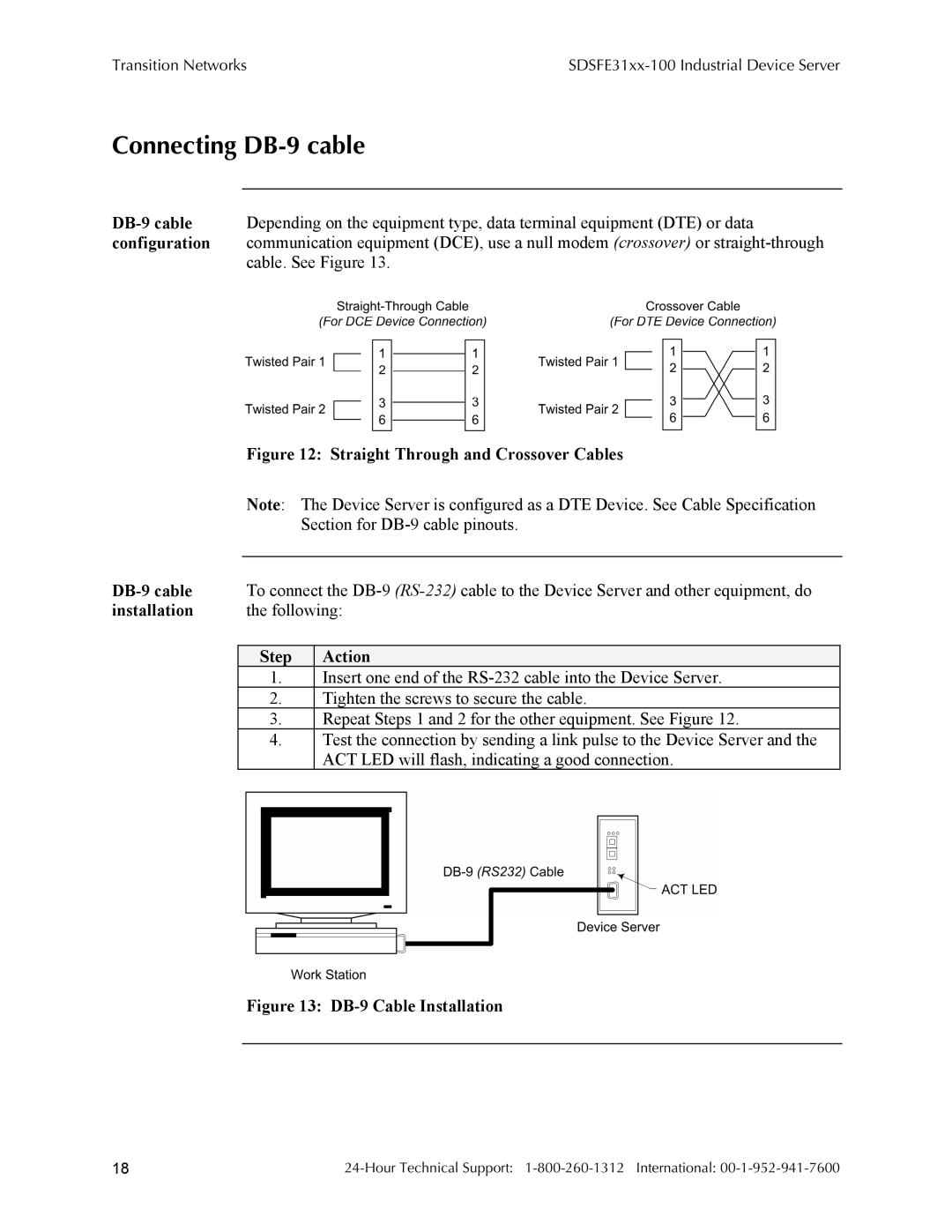
cable. See Figure 13.
| Figure 12: Straight Through and Crossover Cables | |||
| Note: The Device Server is configured as a DTE Device. See Cable Specification | |||
|
| Section for | ||
|
|
|
| |
| To connect the | |||
installation | the following: | |||
|
|
|
|
|
| Step |
| Action | |
| 1. |
| Insert one end of the |
|
| 2. |
| Tighten the screws to secure the cable. |
|
| 3. |
| Repeat Steps 1 and 2 for the other equipment. See Figure 12. |
|
| 4. |
| Test the connection by sending a link pulse to the Device Server and the |
|
|
|
| ACT LED will flash, indicating a good connection. |
|
Figure 13: DB-9 Cable Installation
18 |
